


Discover how RECOM’s 3D Power Packaging® boosts efficiency and power density in DC/DC converters, regulators, and SMD modules for key applications.

Search Results for "null"
Filter by:
| Part Number | Product Category | Power (W) | Vin (V) | Vout 1 (V) | Package Style | Isolation (kV) | |||||
|---|---|---|---|---|---|---|---|---|---|---|---|
| 1 |

|
RYK-053.3S/H
Focus
| DC/DC | 1 | 5 | 3.3 | SIP7 | 4 | |||
| 2 |
|
RYK-0505S/H
Focus
| DC/DC | 1 | 5 | 5 | SIP7 | 4 | |||
| 3 |

|
RY-2424S/P
| DC/DC | 1 | 24 | 24 | SIP7 | 1 | |||
| 4 |
|
RY-2424S
| DC/DC | 1 | 24 | 24 | SIP7 | 1 | |||
| 5 |
|
RY-2424D/P
| DC/DC | 1 | 24 | 24 | SIP7 | 1 | |||
| 6 |
|
RY-2424D
| DC/DC | 1 | 24 | 24 | SIP7 | 1 | |||
| 7 |
|
RY-2415S/P
| DC/DC | 1 | 24 | 15 | SIP7 | 1 | |||
| 8 |
|
RY-2415S
| DC/DC | 1 | 24 | 15 | SIP7 | 1 | |||
| 9 |
|
RY-2415D/P
| DC/DC | 1 | 24 | 15 | SIP7 | 1 | |||
| 10 |
|
RY-2415D
| DC/DC | 1 | 24 | 15 | SIP7 | 1 | |||
| 11 |
|
RY-2412S/P
| DC/DC | 1 | 24 | 12 | SIP7 | 1 | |||
| 12 |
|
RY-2412S
| DC/DC | 1 | 24 | 12 | SIP7 | 1 | |||
| 13 |
|
RY-2412D/P
| DC/DC | 1 | 24 | 12 | SIP7 | 1 | |||
| 14 |
|
RY-2412D
| DC/DC | 1 | 24 | 12 | SIP7 | 1 | |||
| 15 |
|
RY-2409S/P
| DC/DC | 1 | 24 | 9 | SIP7 | 1 | |||
| 16 |
|
RY-2409S
| DC/DC | 1 | 24 | 9 | SIP7 | 1 | |||
| 17 |
|
RY-2409D/P
| DC/DC | 1 | 24 | 9 | SIP7 | 1 | |||
| 18 |
|
RY-2409D
| DC/DC | 1 | 24 | 9 | SIP7 | 1 | |||
| 19 |
|
RY-2405S/P
| DC/DC | 1 | 24 | 5 | SIP7 | 1 | |||
| 20 |
|
RY-2405S
| DC/DC | 1 | 24 | 5 | SIP7 | 1 | |||
| 21 |
|
RY-2405D/P
| DC/DC | 1 | 24 | 5 | SIP7 | 1 | |||
| 22 |
|
RY-2405D
| DC/DC | 1 | 24 | 5 | SIP7 | 1 | |||
| 23 |
|
RY-1524S/P
| DC/DC | 1 | 15 | 24 | SIP7 | 1 | |||
| 24 |
|
RY-1524S
| DC/DC | 1 | 15 | 24 | SIP7 | 1 | |||
| 25 |
|
RY-1524D/P
| DC/DC | 1 | 15 | 24 | SIP7 | 1 | |||
| 26 |
|
RY-1524D
| DC/DC | 1 | 15 | 24 | SIP7 | 1 | |||
| 27 |
|
RY-1515S/P
| DC/DC | 1 | 15 | 15 | SIP7 | 1 | |||
| 28 |
|
RY-1515S
| DC/DC | 1 | 15 | 15 | SIP7 | 1 | |||
| 29 |
|
RY-1515D/P
| DC/DC | 1 | 15 | 15 | SIP7 | 1 | |||
| 30 |
|
RY-1515D
| DC/DC | 1 | 15 | 15 | SIP7 | 1 | |||
| 31 |
|
RY-1512S/P
| DC/DC | 1 | 15 | 12 | SIP7 | 1 | |||
| 32 |
|
RY-1512S
| DC/DC | 1 | 15 | 12 | SIP7 | 1 | |||
| 33 |
|
RY-1512D/P
| DC/DC | 1 | 15 | 12 | SIP7 | 1 | |||
| 34 |
|
RY-1512D
| DC/DC | 1 | 15 | 12 | SIP7 | 1 | |||
| 35 |
|
RY-1509S/P
| DC/DC | 1 | 15 | 9 | SIP7 | 1 | |||
| 36 |
|
RY-1509S
| DC/DC | 1 | 15 | 9 | SIP7 | 1 | |||
| 37 |
|
RY-1509D/P
| DC/DC | 1 | 15 | 9 | SIP7 | 1 | |||
| 38 |
|
RY-1509D
| DC/DC | 1 | 15 | 9 | SIP7 | 1 | |||
| 39 |
|
RY-1505S/P
| DC/DC | 1 | 15 | 5 | SIP7 | 1 | |||
| 40 |
|
RY-1505S
| DC/DC | 1 | 15 | 5 | SIP7 | 1 | |||
| 41 |
|
RY-1505D/P
| DC/DC | 1 | 15 | 5 | SIP7 | 1 | |||
| 42 |
|
RY-1505D
| DC/DC | 1 | 15 | 5 | SIP7 | 1 | |||
| 43 |
|
RY-1224S/P
| DC/DC | 1 | 12 | 24 | SIP7 | 1 | |||
| 44 |
|
RY-1224S
| DC/DC | 1 | 12 | 24 | SIP7 | 1 | |||
| 45 |
|
RY-1224D/P
| DC/DC | 1 | 12 | 24 | SIP7 | 1 | |||
| 46 |
|
RY-1224D
| DC/DC | 1 | 12 | 24 | SIP7 | 1 | |||
| 47 |
|
RY-1215S/P
| DC/DC | 1 | 12 | 15 | SIP7 | 1 | |||
| 48 |
|
RY-1215S
| DC/DC | 1 | 12 | 15 | SIP7 | 1 | |||
| 49 |
|
RY-1215D/P
| DC/DC | 1 | 12 | 15 | SIP7 | 1 | |||
| 50 |
|
RY-1215D
| DC/DC | 1 | 12 | 15 | SIP7 | 1 | |||
| 51 |
|
RY-1212S/P
| DC/DC | 1 | 12 | 12 | SIP7 | 1 | |||
| 52 |
|
RY-1212S
| DC/DC | 1 | 12 | 12 | SIP7 | 1 | |||
| 53 |
|
RY-1212D/P
| DC/DC | 1 | 12 | 12 | SIP7 | 1 | |||
| 54 |
|
RY-1212D
| DC/DC | 1 | 12 | 12 | SIP7 | 1 | |||
| 55 |
|
RY-1209S/P
| DC/DC | 1 | 12 | 9 | SIP7 | 1 | |||
| 56 |
|
RY-1209S
| DC/DC | 1 | 12 | 9 | SIP7 | 1 | |||
| 57 |
|
RY-1209D/P
| DC/DC | 1 | 12 | 9 | SIP7 | 1 | |||
| 58 |
|
RY-1209D
| DC/DC | 1 | 12 | 9 | SIP7 | 1 | |||
| 59 |
|
RY-1205S/P
| DC/DC | 1 | 12 | 5 | SIP7 | 1 | |||
| 60 |
|
RY-1205S
| DC/DC | 1 | 12 | 5 | SIP7 | 1 | |||
| 61 |
|
RY-1205D/P
| DC/DC | 1 | 12 | 5 | SIP7 | 1 | |||
| 62 |
|
RY-1205D
| DC/DC | 1 | 12 | 5 | SIP7 | 1 | |||
| 63 |
|
RY-0924S/P
| DC/DC | 1 | 9 | 24 | SIP7 | 1 | |||
| 64 |
|
RY-0924S
| DC/DC | 1 | 9 | 24 | SIP7 | 1 | |||
| 65 |
|
RY-0924D/P
| DC/DC | 1 | 9 | 24 | SIP7 | 1 | |||
| 66 |
|
RY-0924D
| DC/DC | 1 | 9 | 24 | SIP7 | 1 | |||
| 67 |
|
RY-0915S/P
| DC/DC | 1 | 9 | 15 | SIP7 | 1 | |||
| 68 |
|
RY-0915S
| DC/DC | 1 | 9 | 15 | SIP7 | 1 | |||
| 69 |
|
RY-0915D/P
| DC/DC | 1 | 9 | 15 | SIP7 | 1 | |||
| 70 |
|
RY-0915D
| DC/DC | 1 | 9 | 15 | SIP7 | 1 | |||
| 71 |
|
RY-0912S/P
| DC/DC | 1 | 9 | 12 | SIP7 | 1 | |||
| 72 |
|
RY-0912S
| DC/DC | 1 | 9 | 12 | SIP7 | 1 | |||
| 73 |
|
RY-0912D/P
| DC/DC | 1 | 9 | 12 | SIP7 | 1 | |||
| 74 |
|
RY-0912D
| DC/DC | 1 | 9 | 12 | SIP7 | 1 | |||
| 75 |
|
RY-0909S/P
| DC/DC | 1 | 9 | 9 | SIP7 | 1 | |||
| 76 |
|
RY-0909S
| DC/DC | 1 | 9 | 9 | SIP7 | 1 | |||
| 77 |
|
RY-0909D/P
| DC/DC | 1 | 9 | 9 | SIP7 | 1 | |||
| 78 |
|
RY-0909D
| DC/DC | 1 | 9 | 9 | SIP7 | 1 | |||
| 79 |
|
RY-0905S/P
| DC/DC | 1 | 9 | 5 | SIP7 | 1 | |||
| 80 |
|
RY-0905S
| DC/DC | 1 | 9 | 5 | SIP7 | 1 | |||
| 81 |
|
RY-0905D/P
| DC/DC | 1 | 9 | 5 | SIP7 | 1 | |||
| 82 |
|
RY-0905D
| DC/DC | 1 | 9 | 5 | SIP7 | 1 | |||
| 83 |
|
RY-0524S/P
| DC/DC | 1 | 5 | 24 | SIP7 | 1 | |||
| 84 |
|
RY-0524S
| DC/DC | 1 | 5 | 24 | SIP7 | 1 | |||
| 85 |
|
RY-0524D/P
| DC/DC | 1 | 5 | 24 | SIP7 | 1 | |||
| 86 |
|
RY-0524D
| DC/DC | 1 | 5 | 24 | SIP7 | 1 | |||
| 87 |
|
RY-0515S/P
| DC/DC | 1 | 5 | 15 | SIP7 | 1 | |||
| 88 |
|
RY-0515S
| DC/DC | 1 | 5 | 15 | SIP7 | 1 | |||
| 89 |
|
RY-0515D/P
| DC/DC | 1 | 5 | 15 | SIP7 | 1 | |||
| 90 |
|
RY-0515D
| DC/DC | 1 | 5 | 15 | SIP7 | 1 | |||
| 91 |
|
RY-0512S/P
| DC/DC | 1 | 5 | 12 | SIP7 | 1 | |||
| 92 |
|
RY-0512S
| DC/DC | 1 | 5 | 12 | SIP7 | 1 | |||
| 93 |
|
RY-0512D/P
| DC/DC | 1 | 5 | 12 | SIP7 | 1 | |||
| 94 |
|
RY-0512D
| DC/DC | 1 | 5 | 12 | SIP7 | 1 | |||
| 95 |
|
RY-0509S/P
| DC/DC | 1 | 5 | 9 | SIP7 | 1 | |||
| 96 |
|
RY-0509S
| DC/DC | 1 | 5 | 9 | SIP7 | 1 | |||
| 97 |
|
RY-0509D/P
| DC/DC | 1 | 5 | 9 | SIP7 | 1 | |||
| 98 |
|
RY-0509D
| DC/DC | 1 | 5 | 9 | SIP7 | 1 | |||
| 99 |
|
RY-0505S/P
| DC/DC | 1 | 5 | 5 | SIP7 | 1 | |||
| 100 |
|
RY-0505S
| DC/DC | 1 | 5 | 5 | SIP7 | 1 | |||
| 101 |
|
RY-0505D/P
| DC/DC | 1 | 5 | 5 | SIP7 | 1 | |||
| 102 |
|
RY-0505D
| DC/DC | 1 | 5 | 5 | SIP7 | 1 | |||
| 103 |

|
RW2-483.3S/SMD
| DC/DC | 2 | 36 - 72 | 3.3 | SMD 16 Pin | 1 | |||
| 104 |
|
RW2-483.3S/H3/SMD
| DC/DC | 2 | 36 - 72 | 3.3 | SMD 16 Pin | 3 | |||
| 105 |
|
RW2-483.3S/H3/B
| DC/DC | 2 | 36 - 72 | 3.3 | DIP16 Mini | 3 | |||
| 106 |
|
RW2-483.3S/H3
| DC/DC | 2 | 36 - 72 | 3.3 | DIP16 | 3 | |||
| 107 |
|
RW2-483.3S/H2/SMD
| DC/DC | 2 | 36 - 72 | 3.3 | SMD 16 Pin | 2 | |||
| 108 |
|
RW2-483.3S/H2/B
| DC/DC | 2 | 36 - 72 | 3.3 | DIP16 Mini | 2 | |||
| 109 |
|
RW2-483.3S/H2
| DC/DC | 2 | 36 - 72 | 3.3 | DIP16 | 2 | |||
| 110 |
|
RW2-483.3S/B
| DC/DC | 2 | 36 - 72 | 3.3 | DIP16 Mini | 1 | |||
| 111 |
|
RW2-483.3S
| DC/DC | 2 | 36 - 72 | 3.3 | DIP16 | 1 | |||
| 112 |
|
RW2-483.3D/SMD
| DC/DC | 2 | 36 - 72 | 3.3 | SMD 16 Pin | 1 | |||
| 113 |
|
RW2-483.3D/H3/SMD
| DC/DC | 2 | 36 - 72 | 3.3 | SMD 16 Pin | 3 | |||
| 114 |
|
RW2-483.3D/H3/B
| DC/DC | 2 | 36 - 72 | 3.3 | DIP16 Mini | 3 | |||
| 115 |
|
RW2-483.3D/H3
| DC/DC | 2 | 36 - 72 | 3.3 | DIP16 | 3 | |||
| 116 |
|
RW2-483.3D/H2/SMD
| DC/DC | 2 | 36 - 72 | 3.3 | SMD 16 Pin | 2 | |||
| 117 |
|
RW2-483.3D/H2/B
| DC/DC | 2 | 36 - 72 | 3.3 | DIP16 Mini | 2 | |||
| 118 |
|
RW2-483.3D/H2
| DC/DC | 2 | 36 - 72 | 3.3 | DIP16 | 2 | |||
| 119 |
|
RW2-483.3D/B
| DC/DC | 2 | 36 - 72 | 3.3 | DIP16 Mini | 1 | |||
| 120 |
|
RW2-483.3D
| DC/DC | 2 | 36 - 72 | 3.3 | DIP16 | 1 | |||
| 121 |
|
RW2-4815S/SMD
| DC/DC | 2 | 36 - 72 | 15 | SMD 16 Pin | 1 | |||
| 122 |
|
RW2-4815S/H3/SMD
| DC/DC | 2 | 36 - 72 | 15 | SMD 16 Pin | 3 | |||
| 123 |
|
RW2-4815S/H3/B
| DC/DC | 2 | 36 - 72 | 15 | DIP16 Mini | 3 | |||
| 124 |
|
RW2-4815S/H3
| DC/DC | 2 | 36 - 72 | 15 | DIP16 | 3 | |||
| 125 |
|
RW2-4815S/H2/SMD
| DC/DC | 2 | 36 - 72 | 15 | SMD 16 Pin | 2 | |||
| 126 |
|
RW2-4815S/H2/B
| DC/DC | 2 | 36 - 72 | 15 | DIP16 Mini | 2 | |||
| 127 |
|
RW2-4815S/H2
| DC/DC | 2 | 36 - 72 | 15 | DIP16 | 2 | |||
| 128 |
|
RW2-4815S/B
| DC/DC | 2 | 36 - 72 | 15 | DIP16 Mini | 1 | |||
| 129 |
|
RW2-4815S
| DC/DC | 2 | 36 - 72 | 15 | DIP16 | 1 | |||
| 130 |
|
RW2-4815D/SMD
| DC/DC | 2 | 36 - 72 | 15 | SMD 16 Pin | 1 | |||
| 131 |
|
RW2-4815D/H3/SMD
| DC/DC | 2 | 36 - 72 | 15 | SMD 16 Pin | 3 | |||
| 132 |
|
RW2-4815D/H3/B
| DC/DC | 2 | 36 - 72 | 15 | DIP16 Mini | 3 | |||
| 133 |
|
RW2-4815D/H3
| DC/DC | 2 | 36 - 72 | 15 | DIP16 | 3 | |||
| 134 |
|
RW2-4815D/H2/SMD
| DC/DC | 2 | 36 - 72 | 15 | SMD 16 Pin | 2 | |||
| 135 |
|
RW2-4815D/H2/B
| DC/DC | 2 | 36 - 72 | 15 | DIP16 Mini | 2 | |||
| 136 |
|
RW2-4815D/H2
| DC/DC | 2 | 36 - 72 | 15 | DIP16 | 2 | |||
| 137 |
|
RW2-4815D/B
| DC/DC | 2 | 36 - 72 | 15 | DIP16 Mini | 1 | |||
| 138 |
|
RW2-4815D
| DC/DC | 2 | 36 - 72 | 15 | DIP16 | 1 | |||
| 139 |
|
RW2-4812S/SMD
| DC/DC | 2 | 36 - 72 | 12 | SMD 16 Pin | 1 | |||
| 140 |
|
RW2-4812S/H3/SMD
| DC/DC | 2 | 36 - 72 | 12 | SMD 16 Pin | 3 | |||
| 141 |
|
RW2-4812S/H3/B
| DC/DC | 2 | 36 - 72 | 12 | DIP16 Mini | 3 | |||
| 142 |
|
RW2-4812S/H3
| DC/DC | 2 | 36 - 72 | 12 | DIP16 | 3 | |||
| 143 |
|
RW2-4812S/H2/SMD
| DC/DC | 2 | 36 - 72 | 12 | SMD 16 Pin | 2 | |||
| 144 |
|
RW2-4812S/H2/B
| DC/DC | 2 | 36 - 72 | 12 | DIP16 Mini | 2 | |||
| 145 |
|
RW2-4812S/H2
| DC/DC | 2 | 36 - 72 | 12 | DIP16 | 2 | |||
| 146 |
|
RW2-4812S/B
| DC/DC | 2 | 36 - 72 | 12 | DIP16 Mini | 1 | |||
| 147 |
|
RW2-4812S
| DC/DC | 2 | 36 - 72 | 12 | DIP16 | 1 | |||
| 148 |
|
RW2-4812D/SMD
| DC/DC | 2 | 36 - 72 | 12 | SMD 16 Pin | 1 | |||
| 149 |
|
RW2-4812D/H3/SMD
| DC/DC | 2 | 36 - 72 | 12 | SMD 16 Pin | 3 | |||
| 150 |
|
RW2-4812D/H3/B
| DC/DC | 2 | 36 - 72 | 12 | DIP16 Mini | 3 | |||
| 151 |
|
RW2-4812D/H3
| DC/DC | 2 | 36 - 72 | 12 | DIP16 | 3 | |||
| 152 |
|
RW2-4812D/H2/SMD
| DC/DC | 2 | 36 - 72 | 12 | SMD 16 Pin | 2 | |||
| 153 |
|
RW2-4812D/H2/B
| DC/DC | 2 | 36 - 72 | 12 | DIP16 Mini | 2 | |||
| 154 |
|
RW2-4812D/H2
| DC/DC | 2 | 36 - 72 | 12 | DIP16 | 2 | |||
| 155 |
|
RW2-4812D/B
| DC/DC | 2 | 36 - 72 | 12 | DIP16 Mini | 1 | |||
| 156 |
|
RW2-4812D
| DC/DC | 2 | 36 - 72 | 12 | DIP16 | 1 | |||
| 157 |
|
RW2-4809S/SMD
| DC/DC | 2 | 36 - 72 | 9 | SMD 16 Pin | 1 | |||
| 158 |
|
RW2-4809S/H3/SMD
| DC/DC | 2 | 36 - 72 | 9 | SMD 16 Pin | 3 | |||
| 159 |
|
RW2-4809S/H3/B
| DC/DC | 2 | 36 - 72 | 9 | DIP16 Mini | 3 | |||
| 160 |
|
RW2-4809S/H3
| DC/DC | 2 | 36 - 72 | 9 | DIP16 | 3 | |||
| 161 |
|
RW2-4809S/H2/SMD
| DC/DC | 2 | 36 - 72 | 9 | SMD 16 Pin | 2 | |||
| 162 |
|
RW2-4809S/H2/B
| DC/DC | 2 | 36 - 72 | 9 | DIP16 Mini | 2 | |||
| 163 |
|
RW2-4809S/H2
| DC/DC | 2 | 36 - 72 | 9 | DIP16 | 2 | |||
| 164 |
|
RW2-4809S/B
| DC/DC | 2 | 36 - 72 | 9 | DIP16 Mini | 1 | |||
| 165 |
|
RW2-4809S
| DC/DC | 2 | 36 - 72 | 9 | DIP16 | 1 | |||
| 166 |
|
RW2-4809D/SMD
| DC/DC | 2 | 36 - 72 | 9 | SMD 16 Pin | 1 | |||
| 167 |
|
RW2-4809D/H3/SMD
| DC/DC | 2 | 36 - 72 | 9 | SMD 16 Pin | 3 | |||
| 168 |
|
RW2-4809D/H3/B
| DC/DC | 2 | 36 - 72 | 9 | DIP16 Mini | 3 | |||
| 169 |
|
RW2-4809D/H3
| DC/DC | 2 | 36 - 72 | 9 | DIP16 | 3 | |||
| 170 |
|
RW2-4809D/H2/SMD
| DC/DC | 2 | 36 - 72 | 9 | SMD 16 Pin | 2 | |||
| 171 |
|
RW2-4809D/H2/B
| DC/DC | 2 | 36 - 72 | 9 | DIP16 Mini | 2 | |||
| 172 |
|
RW2-4809D/H2
| DC/DC | 2 | 36 - 72 | 9 | DIP16 | 2 | |||
| 173 |
|
RW2-4809D/B
| DC/DC | 2 | 36 - 72 | 9 | DIP16 Mini | 1 | |||
| 174 |
|
RW2-4809D
| DC/DC | 2 | 36 - 72 | 9 | DIP16 | 1 | |||
| 175 |
|
RW2-4805S/SMD
| DC/DC | 2 | 36 - 72 | 5 | SMD 16 Pin | 1 | |||
| 176 |
|
RW2-4805S/H3/SMD
| DC/DC | 2 | 36 - 72 | 5 | SMD 16 Pin | 3 | |||
| 177 |
|
RW2-4805S/H3/B
| DC/DC | 2 | 36 - 72 | 5 | DIP16 Mini | 3 | |||
| 178 |
|
RW2-4805S/H3
| DC/DC | 2 | 36 - 72 | 5 | DIP16 | 3 | |||
| 179 |
|
RW2-4805S/H2/SMD
| DC/DC | 2 | 36 - 72 | 5 | SMD 16 Pin | 2 | |||
| 180 |
|
RW2-4805S/H2/B
| DC/DC | 2 | 36 - 72 | 5 | DIP16 Mini | 2 | |||
| 181 |
|
RW2-4805S/H2
| DC/DC | 2 | 36 - 72 | 5 | DIP16 | 2 | |||
| 182 |
|
RW2-4805S/B
| DC/DC | 2 | 36 - 72 | 5 | DIP16 Mini | 1 | |||
| 183 |
|
RW2-4805S
| DC/DC | 2 | 36 - 72 | 5 | DIP16 | 1 | |||
| 184 |
|
RW2-4805D/SMD
| DC/DC | 2 | 36 - 72 | 5 | SMD 16 Pin | 1 | |||
| 185 |
|
RW2-4805D/H3/SMD
| DC/DC | 2 | 36 - 72 | 5 | SMD 16 Pin | 3 | |||
| 186 |
|
RW2-4805D/H3/B
| DC/DC | 2 | 36 - 72 | 5 | DIP16 Mini | 3 | |||
| 187 |
|
RW2-4805D/H3
| DC/DC | 2 | 36 - 72 | 5 | DIP16 | 3 | |||
| 188 |
|
RW2-4805D/H2/SMD
| DC/DC | 2 | 36 - 72 | 5 | SMD 16 Pin | 2 | |||
| 189 |
|
RW2-4805D/H2/B
| DC/DC | 2 | 36 - 72 | 5 | DIP16 Mini | 2 | |||
| 190 |
|
RW2-4805D/H2
| DC/DC | 2 | 36 - 72 | 5 | DIP16 | 2 | |||
| 191 |
|
RW2-4805D/B
| DC/DC | 2 | 36 - 72 | 5 | DIP16 Mini | 1 | |||
| 192 |
|
RW2-4805D
| DC/DC | 2 | 36 - 72 | 5 | DIP16 | 1 | |||
| 193 |
|
RW2-243.3S/SMD
| DC/DC | 2 | 18 - 36 | 3.3 | SMD 16 Pin | 1 | |||
| 194 |
|
RW2-243.3S/H3/SMD
| DC/DC | 2 | 18 - 36 | 3.3 | SMD 16 Pin | 3 | |||
| 195 |
|
RW2-243.3S/H3/B
| DC/DC | 2 | 18 - 36 | 3.3 | DIP16 Mini | 3 | |||
| 196 |
|
RW2-243.3S/H3
| DC/DC | 2 | 18 - 36 | 3.3 | DIP16 | 3 | |||
| 197 |
|
RW2-243.3S/H2/SMD
| DC/DC | 2 | 18 - 36 | 3.3 | SMD 16 Pin | 2 | |||
| 198 |
|
RW2-243.3S/H2/B
| DC/DC | 2 | 18 - 36 | 3.3 | DIP16 Mini | 2 | |||
| 199 |
|
RW2-243.3S/H2
| DC/DC | 2 | 18 - 36 | 3.3 | DIP16 | 2 | |||
| 200 |
|
RW2-243.3S/B
| DC/DC | 2 | 18 - 36 | 3.3 | DIP16 Mini | 1 | |||
| 201 |
|
RW2-243.3S
| DC/DC | 2 | 18 - 36 | 3.3 | DIP16 | 1 | |||
| 202 |
|
RW2-243.3D/SMD
| DC/DC | 2 | 18 - 36 | 3.3 | SMD 16 Pin | 1 | |||
| 203 |
|
RW2-243.3D/H3/SMD
| DC/DC | 2 | 18 - 36 | 3.3 | SMD 16 Pin | 3 | |||
| 204 |
|
RW2-243.3D/H3/B
| DC/DC | 2 | 18 - 36 | 3.3 | DIP16 Mini | 3 | |||
| 205 |
|
RW2-243.3D/H3
| DC/DC | 2 | 18 - 36 | 3.3 | DIP16 | 3 | |||
| 206 |
|
RW2-243.3D/H2/SMD
| DC/DC | 2 | 18 - 36 | 3.3 | SMD 16 Pin | 2 | |||
| 207 |
|
RW2-243.3D/H2/B
| DC/DC | 2 | 18 - 36 | 3.3 | DIP16 Mini | 2 | |||
| 208 |
|
RW2-243.3D/H2
| DC/DC | 2 | 18 - 36 | 3.3 | DIP16 | 2 | |||
| 209 |
|
RW2-243.3D/B
| DC/DC | 2 | 18 - 36 | 3.3 | DIP16 Mini | 1 | |||
| 210 |
|
RW2-243.3D
| DC/DC | 2 | 18 - 36 | 3.3 | DIP16 | 1 | |||
| 211 |
|
RW2-2415S/SMD
| DC/DC | 2 | 18 - 36 | 15 | SMD 16 Pin | 1 | |||
| 212 |
|
RW2-2415S/H3/SMD
| DC/DC | 2 | 18 - 36 | 15 | SMD 16 Pin | 3 | |||
| 213 |
|
RW2-2415S/H3/B
| DC/DC | 2 | 18 - 36 | 15 | DIP16 Mini | 3 | |||
| 214 |
|
RW2-2415S/H3
| DC/DC | 2 | 18 - 36 | 15 | DIP16 | 3 | |||
| 215 |
|
RW2-2415S/H2/SMD
| DC/DC | 2 | 18 - 36 | 15 | SMD 16 Pin | 2 | |||
| 216 |
|
RW2-2415S/H2/B
| DC/DC | 2 | 18 - 36 | 15 | DIP16 Mini | 2 | |||
| 217 |
|
RW2-2415S/H2
| DC/DC | 2 | 18 - 36 | 15 | DIP16 | 2 | |||
| 218 |
|
RW2-2415S/B
| DC/DC | 2 | 18 - 36 | 15 | DIP16 Mini | 1 | |||
| 219 |
|
RW2-2415S
| DC/DC | 2 | 18 - 36 | 15 | DIP16 | 1 | |||
| 220 |
|
RW2-2415D/SMD
| DC/DC | 2 | 18 - 36 | 15 | SMD 16 Pin | 1 | |||
| 221 |
|
RW2-2415D/H3/SMD
| DC/DC | 2 | 18 - 36 | 15 | SMD 16 Pin | 3 | |||
| 222 |
|
RW2-2415D/H3/B
| DC/DC | 2 | 18 - 36 | 15 | DIP16 Mini | 3 | |||
| 223 |
|
RW2-2415D/H3
| DC/DC | 2 | 18 - 36 | 15 | DIP16 | 3 | |||
| 224 |
|
RW2-2415D/H2/SMD
| DC/DC | 2 | 18 - 36 | 15 | SMD 16 Pin | 2 | |||
| 225 |
|
RW2-2415D/H2/B
| DC/DC | 2 | 18 - 36 | 15 | DIP16 Mini | 2 | |||
| 226 |
|
RW2-2415D/H2
| DC/DC | 2 | 18 - 36 | 15 | DIP16 | 2 | |||
| 227 |
|
RW2-2415D/B
| DC/DC | 2 | 18 - 36 | 15 | DIP16 Mini | 1 | |||
| 228 |
|
RW2-2415D
| DC/DC | 2 | 18 - 36 | 15 | DIP16 | 1 | |||
| 229 |
|
RW2-2412S/SMD
| DC/DC | 2 | 18 - 36 | 12 | SMD 16 Pin | 1 | |||
| 230 |
|
RW2-2412S/H3/SMD
| DC/DC | 2 | 18 - 36 | 12 | SMD 16 Pin | 3 | |||
| 231 |
|
RW2-2412S/H3/B
| DC/DC | 2 | 18 - 36 | 12 | DIP16 Mini | 3 | |||
| 232 |
|
RW2-2412S/H3
| DC/DC | 2 | 18 - 36 | 12 | DIP16 | 3 | |||
| 233 |
|
RW2-2412S/H2/SMD
| DC/DC | 2 | 18 - 36 | 12 | SMD 16 Pin | 2 | |||
| 234 |
|
RW2-2412S/H2/B
| DC/DC | 2 | 18 - 36 | 12 | DIP16 Mini | 2 | |||
| 235 |
|
RW2-2412S/H2
| DC/DC | 2 | 18 - 36 | 12 | DIP16 | 2 | |||
| 236 |
|
RW2-2412S/B
| DC/DC | 2 | 18 - 36 | 12 | DIP16 Mini | 1 | |||
| 237 |
|
RW2-2412S
| DC/DC | 2 | 18 - 36 | 12 | DIP16 | 1 | |||
| 238 |
|
RW2-2412D/SMD
| DC/DC | 2 | 18 - 36 | 12 | SMD 16 Pin | 1 | |||
| 239 |
|
RW2-2412D/H3/SMD
| DC/DC | 2 | 18 - 36 | 12 | SMD 16 Pin | 3 | |||
| 240 |
|
RW2-2412D/H3/B
| DC/DC | 2 | 18 - 36 | 12 | DIP16 Mini | 3 | |||
| 241 |
|
RW2-2412D/H3
| DC/DC | 2 | 18 - 36 | 12 | DIP16 | 3 | |||
| 242 |
|
RW2-2412D/H2/SMD
| DC/DC | 2 | 18 - 36 | 12 | SMD 16 Pin | 2 | |||
| 243 |
|
RW2-2412D/H2/B
| DC/DC | 2 | 18 - 36 | 12 | DIP16 Mini | 2 | |||
| 244 |
|
RW2-2412D/H2
| DC/DC | 2 | 18 - 36 | 12 | DIP16 | 2 | |||
| 245 |
|
RW2-2412D/B
| DC/DC | 2 | 18 - 36 | 12 | DIP16 Mini | 1 | |||
| 246 |
|
RW2-2412D
| DC/DC | 2 | 18 - 36 | 12 | DIP16 | 1 | |||
| 247 |
|
RW2-2409S/SMD
| DC/DC | 2 | 18 - 36 | 9 | SMD 16 Pin | 1 | |||
| 248 |
|
RW2-2409S/H3/SMD
| DC/DC | 2 | 18 - 36 | 9 | SMD 16 Pin | 3 | |||
| 249 |
|
RW2-2409S/H3/B
| DC/DC | 2 | 18 - 36 | 9 | DIP16 Mini | 3 | |||
| 250 |
|
RW2-2409S/H3
| DC/DC | 2 | 18 - 36 | 9 | DIP16 | 3 |
| Series | |||||||
|---|---|---|---|---|---|---|---|
| 1 |

|
R-78CK-0.5
Focus
(4 products)
|
|
| |||
| 2 |

|
R-78HE-0.3
Focus
(1 product)
|
|
| |||
| 3 |
|
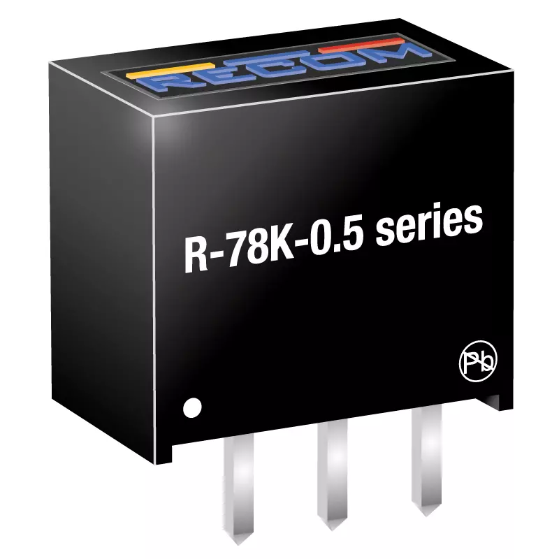
R-78K-0.5
Focus
(9 products)
|
|
| |||
| 4 |

|
R-78K-1.0
Focus
(7 products)
|
|
| |||
| 5 |

|
R-78K-2.0
Focus
(18 products)
|
|
| |||
| 6 |

|
R12C2T12/R
Focus
(2 products)
|
|
| |||
| 7 |

|
R12C2T25/R
Focus
(2 products)
|
|
| |||
| 8 |

|
R15C2T25/R
Focus
(2 products)
|
|
| |||
| 9 |

|
R1DX
Focus
(16 products)
|
|
| |||
| 10 |

|
R1M
Focus
(27 products)
|
|
| |||
| 11 |

|
R1S
Focus
(600 products)
|
|
| |||
| 12 |

|
R1SE
Focus
(4 products)
|
|
| |||
| 13 |

|
R1SE/H2
Focus
(6 products)
|
|
| |||
| 14 |

|
R1SX
Focus
(8 products)
|
|
| |||
| 15 |

|
R24C2T25
Focus
(2 products)
|
|
| |||
| 16 |

|
R24C2T25/R
Focus
(2 products)
|
|
| |||
| 17 |

|
R2M
Focus
(54 products)
|
|
| |||
| 18 |
|
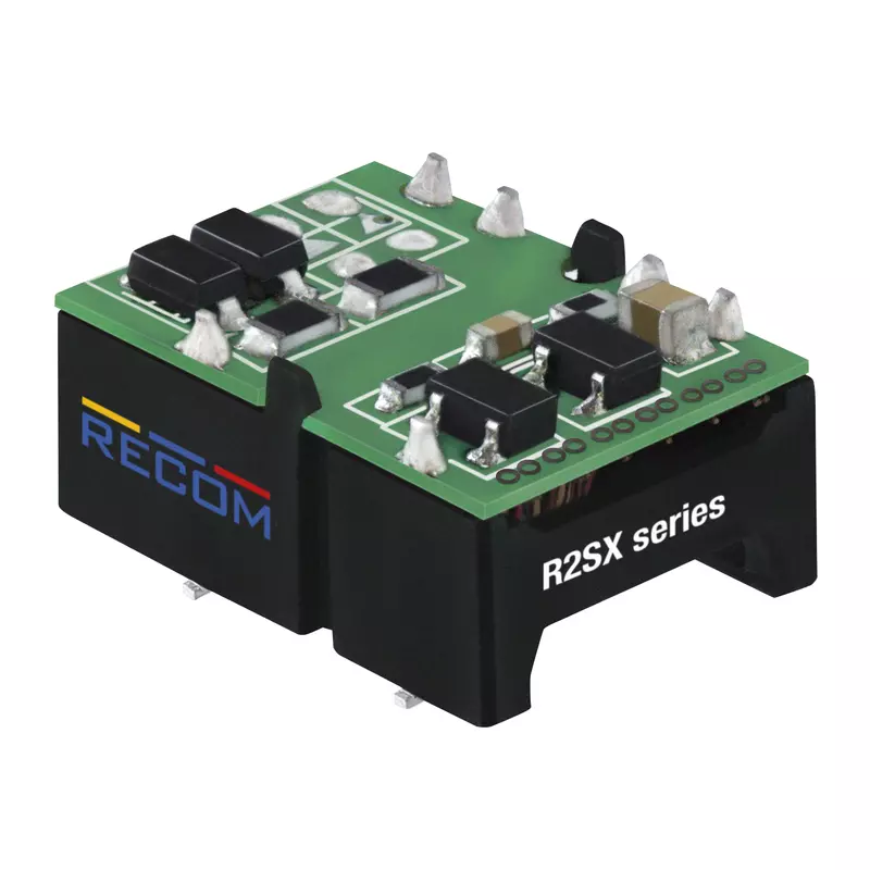
R2SX
Focus
(24 products)
|
|
| |||
| 19 |
|
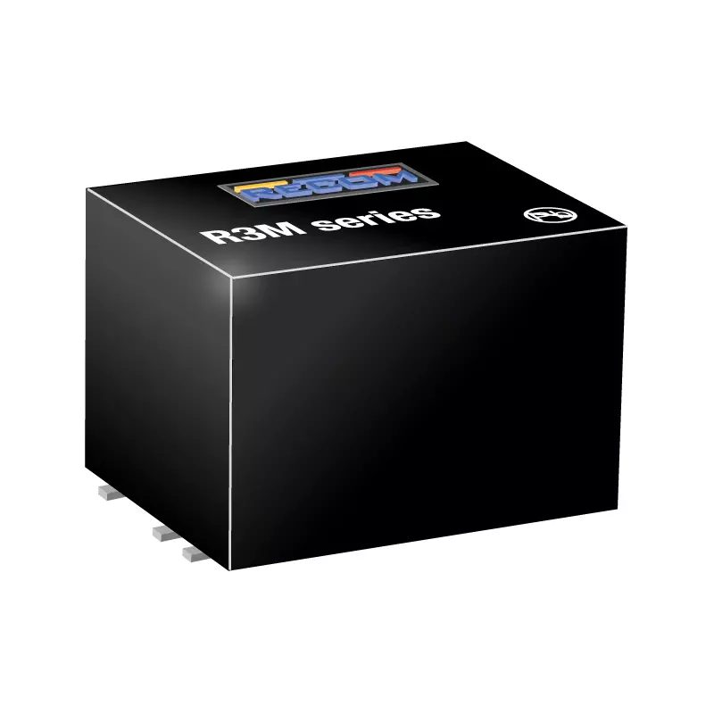
R3M
Focus
(27 products)
|
|
| |||
| 20 |

|
R5M
Focus
(18 products)
|
|
| |||
| 21 |

|
R9C1T18/R
Focus
(2 products)
|
|
| |||
| 22 |

|
RA3
Focus
(32 products)
|
|
| |||
| 23 |

|
RAC02E-K/277
Focus
(5 products)
|
|
| |||
| 24 |

|
RAC03-K
Focus
(11 products)
|
|
| |||
| 25 |

|
RAC03E-K/277
Focus
(5 products)
|
|
| |||
| 26 |

|
RAC04NE-K/277
Focus
(8 products)
|
|
| |||
| 27 |

|
RAC05-K/277
Focus
(5 products)
|
|
| |||
| 28 |

|
RAC05-K/480
Focus
(3 products)
|
|
| |||
| 29 |

|
RAC05E-KT
Focus
(5 products)
|
|
| |||
| 30 |
|
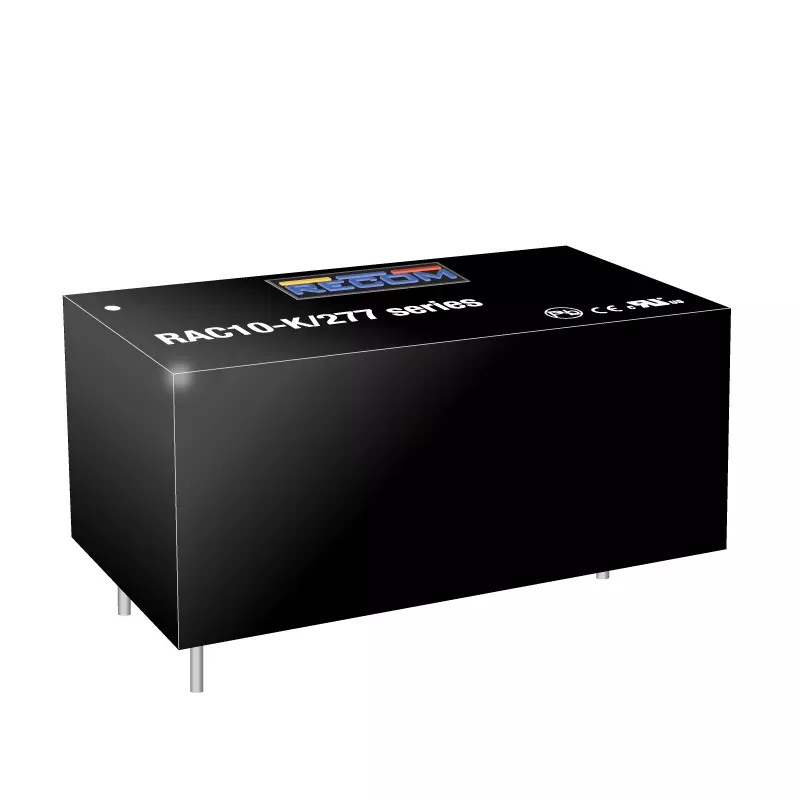
RAC10-K/277
Focus
(8 products)
|
|
| |||
| 31 |

|
RAC10E-K/277
Focus
(5 products)
|
|
| |||
| 32 |

|
RAC15-K/480
Focus
(4 products)
|
|
| |||
| 33 |

|
RAC15-K/WI
Focus
(10 products)
|
|
| |||
| 34 |
|
RAC20-K
Focus
(8 products)
|
|
| |||
| 35 |

|
RAC20-K/277/NE/W
Focus
(2 products)
|
|
| |||
| 36 |

|
RAC20-K/W
Focus
(5 products)
|
|
| |||
| 37 |
|
RAC20E-K/277
Focus
(3 products)
|
|
| |||
| 38 |

|
RAC20NE-K/277
Focus
(10 products)
|
|
| |||
| 39 |

|
RAC20NE-K/277/EPID
Focus
(5 products)
|
|
| |||
| 40 |

|
RAC25-K/480
Focus
(4 products)
|
|
| |||
| 41 |
|
RACM06E-K/277
Focus
(6 products)
|
|
| |||
| 42 |

|
RACM1200-V
Focus
(5 products)
|
|
| |||
| 43 |

|
RACM130E-K
Focus
(10 products)
|
|
| |||
| 44 |

|
RACM140E-K
Focus
(8 products)
|
|
| |||
| 45 |

|
RACM15E-K
Focus
(11 products)
|
|
| |||
| 46 |

|
RACM16E-K/277
Focus
(9 products)
|
|
| |||
| 47 |

|
RACM230-G
Focus
(10 products)
|
|
| |||
| 48 |

|
RACM30-K/277
Focus
(29 products)
|
|
| |||
| 49 |

|
RACM40-K
Focus
(35 products)
|
|
| |||
| 50 |

|
RACM550-G
Focus
(8 products)
|
|
| |||
| 51 |
|
RACM60-K
Focus
(24 products)
|
|
| |||
| 52 |

|
RACM600-L
Focus
(3 products)
|
|
| |||
| 53 |
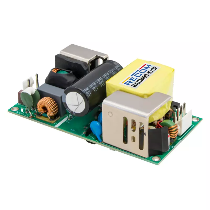
|
RACM90-K
Focus
(10 products)
|
|
| |||
| 54 |

|
RACPRO1-4SP
Focus
(2 products)
|
|
| |||
| 55 |

|
RACPRO1-RD
Focus
신규
(1 product)
|
|
| |||
| 56 |

|
RACPRO1-S120
Focus
신규
(3 products)
|
|
| |||
| 57 |

|
RACPRO1-S240
Focus
신규
(1 product)
|
|
| |||
| 58 |

|
RACPRO1-S240E
Focus
신규
(3 products)
|
|
| |||
| 59 |

|
RACPRO1-S480
Focus
신규
(2 products)
|
|
| |||
| 60 |

|
RACPRO1-T240
Focus
(1 product)
|
|
| |||
| 61 |

|
RACPRO1-T480
Focus
(2 products)
|
|
| |||
| 62 |

|
RACPRO1-T960
Focus
(2 products)
|
|
| |||
| 63 |

|
RACV22-W
Focus
(1 product)
|
|
| |||
| 64 |

|
RB
Focus
(240 products)
|
|
| |||
| 65 |

|
RBA-026
Focus
신규
(2 products)
|
|
| |||
| 66 |

|
RBBA3000
Focus
(1 product)
|
|
| |||
| 67 |

|
RBE
Focus
(1 product)
|
|
| |||
| 68 |

|
RBE-011
Focus
신규
(2 products)
|
|
| |||
| 69 |

|
RBE-014
Focus
신규
(2 products)
|
|
| |||
| 70 |

|
RBE-017
Focus
신규
(2 products)
|
|
| |||
| 71 |

|
RBE-023
Focus
신규
(2 products)
|
|
| |||
| 72 |

|
RBE-024
Focus
신규
(2 products)
|
|
| |||
| 73 |

|
RBE-025
Focus
신규
(2 products)
|
|
| |||
| 74 |

|
RBE-027
Focus
신규
(2 products)
|
|
| |||
| 75 |

|
RBE-029
Focus
신규
(2 products)
|
|
| |||
| 76 |

|
RBE-030
Focus
신규
(2 products)
|
|
| |||
| 77 |

|
RBE-038
Focus
신규
(2 products)
|
|
| |||
| 78 |

|
RCD-24
Focus
(45 products)
|
|
| |||
| 79 |

|
RCDE-48
Focus
(3 products)
|
|
| |||
| 80 |

|
REC10K-AW
Focus
(20 products)
|
|
| |||
| 81 |

|
REC10K-RW
Focus
(20 products)
|
|
| |||
| 82 |

|
REC150H-UW
Focus
(5 products)
|
|
| |||
| 83 |

|
REC20K-Z
Focus
(16 products)
|
|
| |||
| 84 |

|
REC300H-W
Focus
(4 products)
|
|
| |||
| 85 |

|
REC30E-Z
Focus
(14 products)
|
|
| |||
| 86 |

|
REC30K
Focus
(27 products)
|
|
| |||
| 87 |
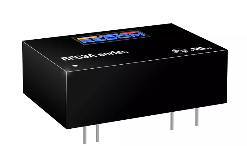
|
REC3A-W
Focus
(4 products)
|
|
| |||
| 88 |

|
REC5A-W
Focus
(4 products)
|
|
| |||
| 89 |

|
REC5K-AW
Focus
(1 product)
|
|
| |||
| 90 |

|
REC5K-RW
Focus
(2 products)
|
|
| |||
| 91 |

|
REC6A-W
Focus
(4 products)
|
|
| |||
| 92 |

|
REC6K-AW
Focus
신규
(18 products)
|
|
| |||
| 93 |

|
REC6K-RW
Focus
신규
(18 products)
|
|
| |||
| 94 |

|
REDIIN120
Focus
(3 products)
|
|
| |||
| 95 |

|
REDIIN240
Focus
(2 products)
|
|
| |||
| 96 |

|
REDIIN480
Focus
(2 products)
|
|
| |||
| 97 |

|
REE
Focus
(1 product)
|
|
| |||
| 98 |

|
REFIN2U-S
Focus
신규
(3 products)
|
|
| |||
| 99 |

|
REM1
Focus
(12 products)
|
|
| |||
| 100 |

|
REM10
Focus
(96 products)
|
|
| |||
| 101 |

|
REM2A
Focus
(64 products)
|
|
| |||
| 102 |

|
REM3.5E
Focus
(360 products)
|
|
| |||
| 103 |

|
REM4A
Focus
(56 products)
|
|
| |||
| 104 |

|
REM5E
Focus
(360 products)
|
|
| |||
| 105 |

|
REM60-W
Focus
(14 products)
|
|
| |||
| 106 |

|
REM6E
Focus
(210 products)
|
|
| |||
| 107 |

|
RFB
Focus
(1 product)
|
|
| |||
| 108 |

|
RFM
Focus
(1 product)
|
|
| |||
| 109 |

|
RFMM
Focus
(1 product)
|
|
| |||
| 110 |

|
RK
Focus
(64 products)
|
|
| |||
| 111 |

|
RKE
Focus
(3 products)
|
|
| |||
| 112 |

|
RKK
Focus
(1 product)
|
|
| |||
| 113 |
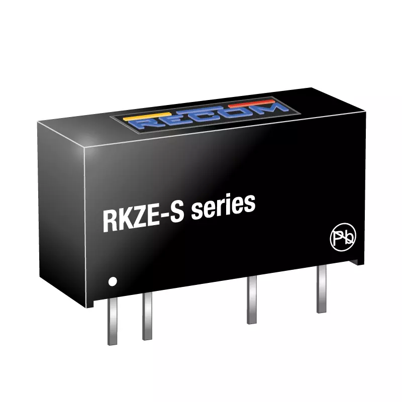
|
RKZE
Focus
(112 products)
|
|
| |||
| 114 |
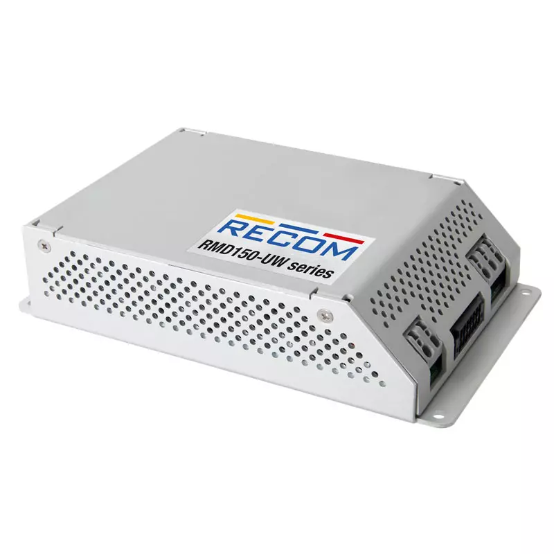
|
RMD150-UW
Focus
(2 products)
|
|
| |||
| 115 |
|
RMD300-UW
Focus
(3 products)
|
|
| |||
| 116 |
|
RMD40-UW
Focus
신규
(4 products)
|
|
| |||
| 117 |
|
RMD500-EW
Focus
(1 product)
|
|
| |||
| 118 |

|
RMD75-UW
Focus
신규
(4 products)
|
|
| |||
| 119 |

|
RMOD300-UW
Focus
(11 products)
|
|
| |||
| 120 |

|
RMOD360-UW
Focus
(2 products)
|
|
| |||
| 121 |

|
RMOD400-EW
Focus
(1 product)
|
|
| |||
| 122 |
|
RMOD400-W
Focus
(2 products)
|
|
| |||
| 123 |

|
RMOD4000-EW
Focus
(2 products)
|
|
| |||
| 124 |

|
RMOD600-EW
Focus
(1 product)
|
|
| |||
| 125 |

|
RMOD600-W
Focus
(1 product)
|
|
| |||
| 126 |

|
RMR-003
Focus
신규
(2 products)
|
|
| |||
| 127 |

|
RMR-004
Focus
신규
(2 products)
|
|
| |||
| 128 |

|
RMR-005
Focus
신규
(2 products)
|
|
| |||
| 129 |

|
RMR-006
Focus
신규
(2 products)
|
|
| |||
| 130 |

|
RMR-007
Focus
신규
(2 products)
|
|
| |||
| 131 |

|
RMR-008
Focus
신규
(2 products)
|
|
| |||
| 132 |

|
RMR-009
Focus
신규
(2 products)
|
|
| |||
| 133 |

|
RMR-010
Focus
신규
(2 products)
|
|
| |||
| 134 |

|
RMR-012
Focus
신규
(2 products)
|
|
| |||
| 135 |

|
RMR-013
Focus
신규
(2 products)
|
|
| |||
| 136 |

|
RMR-015
Focus
신규
(2 products)
|
|
| |||
| 137 |

|
RMR-016
Focus
신규
(2 products)
|
|
| |||
| 138 |

|
RMR-018
Focus
신규
(2 products)
|
|
| |||
| 139 |

|
RMR-020
Focus
신규
(2 products)
|
|
| |||
| 140 |

|
RMR-028
Focus
신규
(2 products)
|
|
| |||
| 141 |

|
RMR-031
Focus
신규
(2 products)
|
|
| |||
| 142 |

|
RMR-039
Focus
신규
(2 products)
|
|
| |||
| 143 |

|
ROE
Focus
(7 products)
|
|
| |||
| 144 |

|
ROF-78K-0.5
Focus
신규
(7 products)
|
|
| |||
| 145 |

|
RP
Focus
(180 products)
|
|
| |||
| 146 |

|
RP03-RAW
Focus
(8 products)
|
|
| |||
| 147 |

|
RP06-RAW
Focus
(8 products)
|
|
| |||
| 148 |

|
RP08-AW
Focus
(42 products)
|
|
| |||
| 149 |

|
RP10-RAW
Focus
(9 products)
|
|
| |||
| 150 |

|
RP100-FW
Focus
신규
(56 products)
|
|
| |||
| 151 |

|
RP40Q-RUW
Focus
(40 products)
|
|
| |||
| 152 |

|
RP50-AW
Focus
신규
(56 products)
|
|
| |||
| 153 |

|
RP60Q-RUW
Focus
(40 products)
|
|
| |||
| 154 |

|
RPA100E-W
Focus
(2 products)
|
|
| |||
| 155 |

|
RPA20-FR
Focus
(16 products)
|
|
| |||
| 156 |

|
RPA300E
Focus
(1 product)
|
|
| |||
| 157 |

|
RPA40-FR
Focus
(7 products)
|
|
| |||
| 158 |

|
RPE-021
Focus
신규
(1 product)
|
|
| |||
| 159 |

|
RPH-3.0
Focus
(2 products)
|
|
| |||
| 160 |

|
RPH-3.0-EVM-1
Focus
(1 product)
|
|
| |||
| 161 |

|
RPL-1.0
Focus
(2 products)
|
|
| |||
| 162 |

|
RPL-1.0-EVM-1
Focus
(1 product)
|
|
| |||
| 163 |

|
RPL-10
Focus
(2 products)
|
|
| |||
| 164 |

|
RPL-10-EVM-1
Focus
(1 product)
|
|
| |||
| 165 |

|
RPL-20
Focus
(2 products)
|
|
| |||
| 166 |

|
RPL-20-EVM-1
Focus
(1 product)
|
|
| |||
| 167 |

|
RPL-3.0
Focus
(2 products)
|
|
| |||
| 168 |

|
RPL-3.0-EVM-1
Focus
(1 product)
|
|
| |||
| 169 |

|
RPL-5.0
Focus
(2 products)
|
|
| |||
| 170 |

|
RPL-5.0-EVM-1
Focus
(1 product)
|
|
| |||
| 171 |

|
RPM-1.0
Focus
(4 products)
|
|
| |||
| 172 |

|
RPM-2.0
Focus
(4 products)
|
|
| |||
| 173 |

|
RPM-3.0
Focus
(4 products)
|
|
| |||
| 174 |

|
RPM-6.0
Focus
(4 products)
|
|
| |||
| 175 |

|
RPMA-4.5
Focus
(1 product)
|
|
| |||
| 176 |

|
RPMA-8.0
Focus
(1 product)
|
|
| |||
| 177 |

|
RPMB-2.0
Focus
(8 products)
|
|
| |||
| 178 |

|
RPMB-3.0
Focus
(8 products)
|
|
| |||
| 179 |

|
RPMGE-10
Focus
(2 products)
|
|
| |||
| 180 |

|
RPMGH-40
Focus
(2 products)
|
|
| |||
| 181 |

|
RPMGQ-20
Focus
(2 products)
|
|
| |||
| 182 |

|
RPMGS-20
Focus
(2 products)
|
|
| |||
| 183 |

|
RPMH-0.5
Focus
(10 products)
|
|
| |||
| 184 |

|
RPMH-1.5
Focus
(10 products)
|
|
| |||
| 185 |

|
RPMVH-0.5
Focus
신규
(8 products)
|
|
| |||
| 186 |

|
RPX-0.5Q
Focus
(2 products)
|
|
| |||
| 187 |

|
RPX-0.5Q-EVM-1
Focus
(1 product)
|
|
| |||
| 188 |
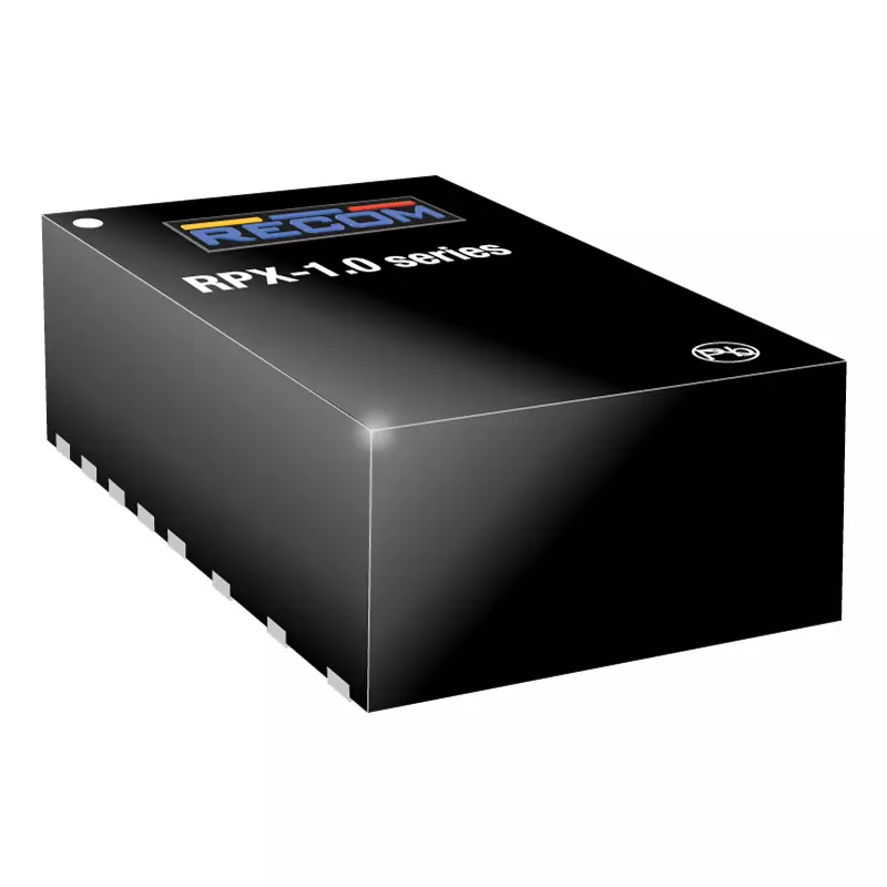
|
RPX-1.0
Focus
(2 products)
|
|
| |||
| 189 |

|
RPX-1.5
Focus
(2 products)
|
|
| |||
| 190 |

|
RPX-1.5Q
Focus
(2 products)
|
|
| |||
| 191 |

|
RPX-1.5Q-EVM-1
Focus
(1 product)
|
|
| |||
| 192 |

|
RPX-2.5
Focus
(2 products)
|
|
| |||
| 193 |

|
RPX-4.0
Focus
(2 products)
|
|
| |||
| 194 |

|
RPX-4.0-EVM-1
Focus
(1 product)
|
|
| |||
| 195 |

|
RPY-1.5Q
Focus
(2 products)
|
|
| |||
| 196 |

|
RPY-1.5Q-EVM-1
Focus
(1 product)
|
|
| |||
| 197 |

|
RPZ-0.5
Focus
(2 products)
|
|
| |||
| 198 |

|
RPZ-0.5-EVM-1
Focus
(1 product)
|
|
| |||
| 199 |

|
RPZ-1.0
Focus
(2 products)
|
|
| |||
| 200 |

|
RPZ-1.0-EVM-1
Focus
(1 product)
|
|
| |||
| 201 |

|
RPZ-2.0
Focus
(2 products)
|
|
| |||
| 202 |

|
RPZ-2.0-EVM-1
Focus
(1 product)
|
|
| |||
| 203 |

|
RPZ-3.0A
Focus
(2 products)
|
|
| |||
| 204 |

|
RPZ-3.0A-EVM-1
Focus
(1 product)
|
|
| |||
| 205 |

|
RPZ-6.0
Focus
(2 products)
|
|
| |||
| 206 |

|
RPZ-6.0-EVM-1
Focus
(1 product)
|
|
| |||
| 207 |

|
RS12-Z
Focus
(10 products)
|
|
| |||
| 208 |

|
RS3E
Focus
(24 products)
|
|
| |||
| 209 |

|
RS3K
Focus
(20 products)
|
|
| |||
| 210 |

|
RSE
Focus
(2 products)
|
|
| |||
| 211 |

|
RSE-Z
Focus
(2 products)
|
|
| |||
| 212 |

|
RSH2
Focus
(80 products)
|
|
| |||
| 213 |

|
RSH3
Focus
(48 products)
|
|
| |||
| 214 |

|
RSK-RUW
Focus
(2 products)
|
|
| |||
| 215 |

|
RSOE
Focus
(2 products)
|
|
| |||
| 216 |

|
RSOE-Z
Focus
(2 products)
|
|
| |||
| 217 |

|
RSOK-Z
Focus
(2 products)
|
|
| |||
| 218 |

|
RTC2-RW
Focus
(4 products)
|
|
| |||
| 219 |

|
RVP001
Focus
신규
(2 products)
|
|
| |||
| 220 |

|
RVP003
Focus
신규
(4 products)
|
|
| |||
| 221 |

|
RVP005
Focus
신규
(2 products)
|
|
| |||
| 222 |

|
RVP010
Focus
신규
(2 products)
|
|
| |||
| 223 |

|
RVP6501
Focus
신규
(2 products)
|
|
| |||
| 224 |

|
RVPW011
Focus
신규
(2 products)
|
|
| |||
| 225 |

|
RVPW012
Focus
신규
(2 products)
|
|
| |||
| 226 |

|
RVPW014
Focus
신규
(2 products)
|
|
| |||
| 227 |

|
RVPW015
Focus
신규
(2 products)
|
|
| |||
| 228 |

|
RVPW016
Focus
신규
(2 products)
|
|
| |||
| 229 |

|
RVS002
Focus
신규
(2 products)
|
|
| |||
| 230 |

|
RVSW013
Focus
신규
(2 products)
|
|
| |||
| 231 |

|
RVSY018
Focus
신규
(2 products)
|
|
| |||
| 232 |
|
RYK
Focus
(2 products)
|
|
| |||
| 233 |

|
RxxC05TExxS
Focus
(2 products)
|
|
| |||
| 234 |

|
RxxC1TFxxS
Focus
(2 products)
|
|
| |||
| 235 |

|
RxxCTExxS
Focus
(2 products)
|
|
| |||
| 236 |

|
RxxCTxxS
Focus
(2 products)
|
|
| |||
| 237 |

|
RxxPxx/R
Focus
(300 products)
|
|
| |||
| 238 |

|
RACM3000-M
Coming Soon
(3 products)
|
|
| |||
| 239 |

|
RMOD2000-EW
Coming Soon
(2 products)
|
|
| |||
| 240 |
DS-RVP001-RMR-003-0505-1
신규
(1 product)
|
|
| ||||
| 241 |
DS-RVP001-RMR-008-0505-1
신규
(1 product)
|
|
| ||||
| 242 |
DS-RVP001-RMR-012-0505-1
신규
(1 product)
|
|
| ||||
| 243 |
DS-RVP001-RMR-028-RVS002-0505-1
신규
(1 product)
|
|
| ||||
| 244 |
DS-RVP003-RMR-004-1212-1
신규
(1 product)
|
|
| ||||
| 245 |
DS-RVP003-RMR-004-1224-2
신규
(1 product)
|
|
| ||||
| 246 |
DS-RVP003-RMR-004-2412-3
신규
(1 product)
|
|
| ||||
| 247 |
DS-RVP003-RMR-004-2424-4
신규
(1 product)
|
|
| ||||
| 248 |
DS-RVP003-RMR-005-1205-1
신규
(1 product)
|
|
| ||||
| 249 |
DS-RVP003-RMR-010-1205-1
신규
(1 product)
|
|
| ||||
| 250 |
DS-RVP003-RMR-010-2405-2
신규
(1 product)
|
|
|
Cost-effective, compact AC/DCs, encapsulated, open frame with cooling options. For medical, IT/multimedia household, and industrial use.
Learn why AC became the standard for power distribution and explore the fundamentals of AC/DC power, mains voltages, frequencies, and three-phase systems.
RECOM의 AC/DC 및 DC/DC 컨버터를 살펴보세요. 표준 애플리케이션에 적합한 신뢰성 높은 전원 솔루션으로, 다양한 산업 분야에서 사용할 수 있는 고효율·고성능 제품입니다.
Cost-effective, 5W, 15W, and 25W PCB mount AC/DCs suit up to nominal 480VAC input for three-phase line to line applications
Here you will find sales and technical ☎ support for all North and South American markets. ► Click here and find out more about that!
Cost-effective, compact, grade 1, automotive-qualified, DC/DC converters and LED drivers with wettable flanks for AOI inspection
RECOM in Bangkok. Office supporting sales, distribution, marketing, FAE and customer service. Directions and maps
Here you will find the official RECOM Blog. ► You can get information about insights from our experts on technology & the power industry!
The AC/DC and DC/DC Books of Knowledge from RECOM are a detailed introduction to the various converter topologies. ☛ Click here!
Do you want to buy product samples? ★ Engineering samples are a very good way to test a design. ► Send us your sample request!
Are you looking ⌕ for a job in an international company? ✏ Get more information and apply now for a job at RECOM!
Quality and environmental compliance certificates and declarations for RECOM processes and products for zero-defect goals
Explore the RECOM range of AC/DC and DC/DC modules for EV chargers and battery systems, supporting OVC III environments and high-power demands up to 30kW.
Compact SIP8 and 1”x1” DC/DC converters from RECOM with isolation, wide input range, and high efficiency for industrial and automation use. Learn more.
On this page you will find all ⓘ information about the company history of RECOM. ☛ Click here and read all about this topic!
Learn about RECOM's compliance, Code of Conduct, CSR, environmental standards, ZVEI Code, and Cyber Resilience Act (CRA).
Contact us
Discover cost-effective AC/DC power supplies from RECOM. Compact, efficient modules designed for industrial and commercial power applications.
RECOM offers cost-effective isolated DC/DC converters, regulated and unregulated, for industrial applications with high temperature and voltage stability.
Save time and cost with RECOM’s high-quality, cost-effective AC/DC and DC/DC power modules, switching regulators, and LED drivers.
Discover RECOM’s cost-effective switching regulators with up to 97% efficiency. Replace linear regulators, eliminate heat-sinks, and simplify PCB integration.
Counterfeit products risk financial, reputation and legal loss. RECOM products should be sourced from authorized distributors
Fulfil your power converter needs with a full-custom, semi-custom, or modified-standard solution from RECOM for all markets and applications.
RECOM의 전원 공급 장치 설계 솔루션을 살펴보세요. 다양한 산업과 애플리케이션에 최적화된 완전 맞춤형 AC/DC 및 DC/DC 컨버터를 제공합니다.
Your power converter specifications meet RECOM’s custom solution. Any product or market, including safety and EMC certification.
On this page you will find a list including all authorised distributors by RECOM. ☛ Click here, select a country & find distributors!
RECOM E-Series from Future electronics. Low cost, DC/DC, AC/DC converters for industrial/consumer applications
RECOM E-Series from Rutronik. Low cost, certified DC/DC, AC/DC converters for industrial/consumer applications
AOI 검사용 웨터블 플랭크가 있는 비용 효율적이고 콤팩트한 등급 1의 자동차 인증 DC/DC
Explore energy harvesting from photovoltaic and thermoelectric sources, plus boost and buck DC/DC converters for low-power wireless devices.
RECOM R-78S IoT demo kit. An evaluation module boosting an AA battery voltage to 3.3V for ST Microelectronics SensorTile
All RECOM events and exhibition dates can be found on this page. ► Inform yourself now & visit us at a trade show!
Inform yourself on this page about the ⚡ high isolated DC/DC converters for gate drivers from RECOM. ➤ Click here & learn more!
RECOM glossary of words and terms used in power conversion and related electronics, in a searchable list
RECOM headquarters in Gmunden, Austria, images, contact details and directions. R&D, test, quality assurance and management
This page contains the worldwide ☎ contact information of RECOM. ► Click here and contact our international company!
RECOM의 의료, 산업, 철도 및 전기차(EV) 응용 분야용 고출력 SMPS를 살펴보세요. 토폴로지, 냉각 및 고급 설계 기능에 대해 알아보세요.
Applications such as transport, defense, medical and industrial often have demanding non-standard specifications, both environmental and functional.
RECOM Power is a ☛ manufacturer of electronic power supply converters. ► Inform yourself about AC/DC and DC/DC converters!
홈 및 빌딩 자동화에 적합한 신뢰성 높은 소형 전원 공급 장치를 확인해 보세요. RECOM은 캡슐형(밀봉형), 오픈 프레임형, DIN 레일형으로 제공되는 2W ~ 330W급 솔루션을 제공합니다.
Find all important information and contact details in the ⓘ imprint of RECOM. You will find more details ➤ on this page!
RECOM offers a wide range of robust ⚡ DC/DC and AC/DC power supplies for the industry. ➤ Click here and get more information!
Explore RECOM’s industrial-grade DC/DC & AC/DC power supplies and switching regulators (0.25W–10kW) for automation, 48V systems, and industrial control.
Explore RECOM's industrial power conversion solutions, including high-power battery chargers, PFC front ends, and DC/DC converters for traction batteries.
Explore RECOM’s efficient AC/DC and DC/DC power supplies for IoT and IIoT: compact, reliable, and low-power solutions for smart homes and industry.
On this page you will find an online isolation calculator for AC and DC. ✏ Click here and find out more about this calculator!
Media Center - Images, Videos
Certified medical power supplies for clinical and home care devices. AC/DC and DC/DC converters with reinforced isolation, low leakage, and 2MOPP compliance.
Explore RECOM’s rugged AC/DC & DC/DC converters, battery conditioners, and bi-directional solutions for e-mobility, including EVs and small transport.
RECOM in Neu Isenburg – headquarters of EMEA sales. Close to Frankfurt downtown and airport. Contact details and directions
On this page you will find all current ⓘ information and news from RECOM. ☛ Click here and get to the newsroom!
Stay informed with the RECOM Newsletter. Sign up and receive exclusive ⓘ information. ☛ Click here and subscribe to our newsletter!
Latest News, Events and Activities by RECOM
RECOM high resolution press images. Photos of RECOM headquarters building in Gmunden Austria, exterior and interior
RECOM quick and thorough podcasts. Powerful podcast presentations on RECOM products, technical and application data
Custom power solutions from RECOM and RPS for harsh and high reliability applications. AC/DC, DC/DC converters and inverters.
If you have any questions, check out our ➜ power supply faqs page. ✏ Click here and inform yourself about the topic!
In our ☛ news section you will find interesting news about our products and other terms. ➤ Click here and read press releases!
RECOM의 제품 검색 도구로 엔지니어링 워크플로를 간소화하세요. 파라미터 검색과 제품 비교 기능을 활용해 최적의 전원 솔루션을 찾을 수 있습니다.
Use RECOM’s Product Comparison tool to compare power supplies, converters, and modules side by side for faster and more accurate product selection.
Publications from RECOM. Reference information - quick selection guide, medical, rail, EMC and Power Control Systems
40W-1200W external fan-less open frame AC/DC power supplies with industrial and medical certifications have high power density
High-specification 1200W Fanless AC/DC for medical applications
High-specification 1200W Fanless AC/DC for medical applications
energy efficient, high-quality, and cost-effective 3W-20W AC/DC Converters
RECOM offers a huge range of DC/DC converters for railway technology. ➤ Here you will find more information about railway power supplies!
RECOM product cosmetic appearance change. Cases change from laser printed to embossed logo for anti-counterfeit measures
Explore RECOM AC/DC and DC/DC converters for test and measurement systems featuring high isolation, low noise, and reliable performance in industrial use.
The RECOM company is active worldwide at several ➤ locations and in different regions. ✏ Get more information now!
높은 dV/dt 스루레이트 스트레스 하에서의 RECOM DC/DC 컨버터 절연 시험에 대해 자세히 알아보세요. 부분방전(PD) 시험을 통해 신뢰성이 입증되었습니다.
Here you will discover many ➥ technical reports and reviews of RECOM. ► Download now and read more information!
Resource Library - Application Notes, Technical Documents...
RECOM products are fully RoHS (Restriction of Hazardous Substances) compliant.
Sales representative contact form. Fill in details for a RECOM sales person to contact you about RECOM or RPS products
Here you can find comprehensive information ⓘ about the safety standards for power supplies. ► Click here and learn more!
On this page you can pick your region to find the right contact person for your support inquiries. ☎ Find support contact now!
At RECOM you can easily request a sample of the desired product online. ➥ Here you can get additional samples from RECOM!
Use RECOM’s Product Selection Guide to identify the right power supplies, converters, and modules based on application and technical requirements.
RECOM in Shanghai, China. Office supporting sales, marketing, FAE and customer service. Directions and maps
RECOM in Singapore. Office supporting sales, distribution, marketing, FAE and customer service. Directions and maps
Here you will find the sitemap of RECOM. ➤ Click here and use our sitemap to quickly find what you are looking for!
Our commitment to sustainability, ethical practices, and environmental responsibility. Learn how we're powering a greener future with efficient power solutions.
Do you have any questions about our products? ➨ Our technical support will help you choose the right power supply for your application!
RECOM office in Tokyo, Japan. Supporting north east Asia region. Directions, contact details and maps
FAQs RECOM products certified to EN/IEC 60950-1. Standards obsolete after 20th December 2020, transition arrangements
RECOM offers rugged AC/DC & DC/DC converters for transportation, rail, and off-highway vehicles. Explore reliable on-board chargers & power solutions.
Youtube company videos of RECOM products and processes, corporate ‘about RECOM’, applications, quality and EMC
RECOM in Vienna office, Austria. AC/DC R&D and technical support, contacts details, map and directions
RECOM's headquarters are located in the middle of Europe in Austria. ✏ Get more information about the power supply manufacturer!
This page contains many whitepapers and documents for download. ► Click here and download ➜ whitepapers online!




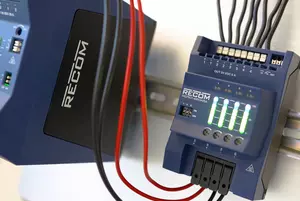

































All AC/DC converters contain a built-in fusible device (either one or more fuses or a fusible resistor), so no external protection is normally necessary. However, some regulations require an external input fuse to protect against short circuits in the AC cabling or PCB tracks leading to the converter. The –ST or RAC-ADAPT options (PCB with screw terminal input and output connections) also contain an external input fuse as standard.
AC/DC converters can tolerate a DC voltage on their outputs when they are not powered up as long as the external DC voltage is lower than their nominal DC output. Therefore the output from the AC/DC adaptor should be connected to an alternate DC supply via OR-ing diodes. This is a useful feature that enables, for example, a board to be powered up and calibrated or tested using a safe low voltage DC bench supply and then only plugged into the mains for a final check after the unit has been reassembled into its case.
All of our AC/DC converters contain a built-in Under Voltage Lock-Out (UVLO) function that will disable the converter if the input voltage is too low to stop the input current getting too high. The UVLO is typically set to around 80V AC.
The main output options are:
Single output, with Vout+ and Vout- pins. This is the most commonly used option.
Dual (bipolar) output, with Vout+, Com and Vout- pins, e.g. +/-15V. Useful for generating bipolar supply rails from a single input voltage rail, e.g, to supply an op-amp.
Dual (asymmetric) output , with Vout+, Com and Vout- pins, e.g. +18/-9V. Useful for IGBT gate driver applications which uses asymmetric supply voltages.
Dual (independent) output, with Vout1+, Vout1- and Vout2+, Vout2-, where the outputs are isolated both from the input and from each other. Useful for supplying a two-channel application using only one converter.
Triple output, with a main Vout+ and Aux+, Com and Aux- pins, e.g. +5V and +/-12V. Useful for applications requiring a single high current supply and an auxiliary supply to power peripherals.
Single output, with Vout+ and Vout- pins. This is the most commonly used option.
Dual (bipolar) output, with Vout+, Com and Vout- pins, e.g. +/-15V. Useful for generating bipolar supply rails from a single input voltage rail, e.g, to supply an op-amp.
Dual (asymmetric) output , with Vout+, Com and Vout- pins, e.g. +18/-9V. Useful for IGBT gate driver applications which uses asymmetric supply voltages.
Dual (independent) output, with Vout1+, Vout1- and Vout2+, Vout2-, where the outputs are isolated both from the input and from each other. Useful for supplying a two-channel application using only one converter.
Triple output, with a main Vout+ and Aux+, Com and Aux- pins, e.g. +5V and +/-12V. Useful for applications requiring a single high current supply and an auxiliary supply to power peripherals.
DC/DC converters are not reverse polarity protected. They will be irreparably damaged if connected the wrong way around. If it is possible or likely that the converter could be reverse polarity connected, then a diode must be used to protect the converter (refer to the Application Notes).
All DC/DC converters can withstand occasional short-duration over-voltage transients (<100ms), but repeated over-voltage conditions can lead to failure. Unregulated DC/DC converters can cope with longer input over-voltage conditions as long as the supply voltage does not exceed the component ratings. The output voltage will also be too high. Regulated DC/DC converters will attempt to regulate an input over-voltage condition so will be more stressed, nevertherless some converters like the REC3.5 and REC6 can withstand 60s input over-voltage conditions (refer to datasheet for limits)
All DC/DC converters can withstand occasional short-duration brown-outs, but repeated under-voltage conditions can lead to failure. For a constant power load, the input current rises exponentially as the input voltage decreases. Unregulated DC/DC converters can cope with longer input under-voltage conditions as long as the increased input current does not exceed the component ratings. The output voltage will also be too low. Unregulated converters do not have an Under-Voltage Lock-Out (UVLO) function. Regulated DC/DC converters will attempt to regulate an input under-voltage condition so will be more stressed, some series are available with an Under-Voltage Lock-Out (UVLO) function, either as standard or as an /X1 option, which disables the converter if the input current is too high. This also stops the converter from attempting to start up too early before the supply voltage has stabilized.
The ratio refers to the input voltage range. For example, a 24V input DC/DC converter with 1:1 input range is specified with 24Vinput +/-10% (21.6V to 26.4V). A 24V input DC/DC converter with 2:1 input range is specified over a two-to-one input voltage range of 18V-36V and a 24V input DC/DC converter with 4:1 input range is specified over a four-to-one input voltage range of 9V-36V.
A non-isolated or switching regulator converter can efficiently reduce or boost a DC input voltage to a lower or higher output voltage.
A switching regulator has the following advantages over an isolated DC/DC converter:
1. As a transformer is not used and the input and output share a common ground, the efficiencies can be very high (>97%). These low losses allow a wider operating temperature and a higher power density compared with isolated converters.
2. A switching regulator can vary the internal on/off duty cycle over a wider range to compensate for changes in load and/or input voltage, thus the converter can work efficiently over an extended input voltage range (7:1 or more) and load range (100:1).
3: Switching regulators often uses a cycle-by-cycle controller IC, so the reaction time to dynamic load changes or short circuit conditions is very fast.
A switching regulator has the following advantages over an isolated DC/DC converter:
1. As a transformer is not used and the input and output share a common ground, the efficiencies can be very high (>97%). These low losses allow a wider operating temperature and a higher power density compared with isolated converters.
2. A switching regulator can vary the internal on/off duty cycle over a wider range to compensate for changes in load and/or input voltage, thus the converter can work efficiently over an extended input voltage range (7:1 or more) and load range (100:1).
3: Switching regulators often uses a cycle-by-cycle controller IC, so the reaction time to dynamic load changes or short circuit conditions is very fast.
An isolated DC/DC converter will translate a DC input voltage to the same or a different DC output voltage which is electrically isolated from the input via an internal transformer. It is commonly used for the following reasons:
1: To break ground loops. Electrical interference on the power rails is blocked from affecting other parts of the circuit, for example, a DC/DC used in a motor controller circuit can provide a low-noise, stable output from a noisy DC supply.
2: To change the reference point of a supply. For example to generate a +5V rail from a -48V telecoms power supply.
3. For safety. For example in medical applications to protect the patient from power supply faults
4: For supply security. For applications with multiple channels, isolating each channel power supply with a separate DC/DC converter means that if any channel is faulty or short-circuited, the remaining channels are unaffected.
1: To break ground loops. Electrical interference on the power rails is blocked from affecting other parts of the circuit, for example, a DC/DC used in a motor controller circuit can provide a low-noise, stable output from a noisy DC supply.
2: To change the reference point of a supply. For example to generate a +5V rail from a -48V telecoms power supply.
3. For safety. For example in medical applications to protect the patient from power supply faults
4: For supply security. For applications with multiple channels, isolating each channel power supply with a separate DC/DC converter means that if any channel is faulty or short-circuited, the remaining channels are unaffected.
A DC/DC converter can have the following connections:
The supply pins, Vin+ and Vin –
The output pins, Vout + and Vout- (plus a common pin for +/- outputs)
A remote control on/off, enable or control pin (usually labelled "CTRL")
A trim pin (to adjust the output voltage up or down)
Sense pins (to compensate for any cable or track resistance losses)
Power OK pin (an output signal to indicate that the output voltage is stable)
The supply pins, Vin+ and Vin –
The output pins, Vout + and Vout- (plus a common pin for +/- outputs)
A remote control on/off, enable or control pin (usually labelled "CTRL")
A trim pin (to adjust the output voltage up or down)
Sense pins (to compensate for any cable or track resistance losses)
Power OK pin (an output signal to indicate that the output voltage is stable)
There are many reasons why you should use a DC/DC converter, but the most common applications are:
- To match the loads to the power supply (e.g. to generate higher, lower or dual outputs from a single source, or to invert a supply rail.)
- To isolate primary and secondary circuits (e.g. for safety reasons or to protect a sensitive circuit from interference)
- To simplify power supplies (e.g. multiple output converters or one converter per rail (point-of-load) can reduce power supply complexity, overall cost and board space requirements while at the same time increasing flexibility, reliability and system efficiency.)
IoT 기기는 배터리 사용 시간을 최대한 늘려야 하므로 고효율, 소형, 저전력 DC/DC 컨버터가 적합합니다.
산업용 전원은 신뢰성, 넓은 입력 전압 범위, 각종 보호 기능, 고효율을 최우선으로 고려해야 합니다. 또한 일반적인 산업 환경 온도 범위인 -40℃ ~ +85℃에서 안정적으로 동작해야 합니다.
마이크로컨트롤러에는 매우 안정적인 전압 레일을 제공하는 저노이즈 DC/DC 컨버터 또는 선형 레귤레이터를 사용해 전원을 공급하는 것이 일반적입니다. 마이크로컨트롤러의 입력 전류는 연산 부하 변화에 따라 급격하게 변동하기 때문에, 부하가 갑자기 변해도 안정성을 유지할 수 있도록 빠른 과도 응답 특성이 요구됩니다.
신뢰성은 부품 품질, 열 관리, 보호 기능 구현, 적절한 전기적 설계에 따라 좌우됩니다.
All RECOM products are RoHS2+ compliant. You can find certificates and Declarations of Conformity on our home page.
Although some of our DC/DC converters contain Class A or Class B EMC filters built in, many of our low cost DC/DC converters contain only simple input filters. The customer can then decide to add an EMC filter individually or for all of the converters together to save costs. External EMI filter suggestions are given in our Application Notes for both Class A and Class B levels. All of our AC/DC converters contain a built-in Class B EMC filter as standard.
The UKCA (UK Conformity Assessed) marking is a new UK product marking that is used for products being placed on the market in Great Britain (England, Wales and Scotland). It applies to the same products that are currently CE marked. The circumstances in which self-declaration of conformity for UKCA marking can be used are the same as for CE marking. Based on current UK rules, RECOM is eligible to self-declare for the UKCA Declaration of Conformity (DoC) as long as the EU and UK regulations remain aligned.
RECOM will make available a separate UKCA Declaration of Conformity (DoC) based on the existing CE Declaration of Conformity (DoC) and test reports (self-declaration). CE marking remains valid for goods placed on the market in Great Britain until 1 January 2023. The UKCA marking must be used for placing goods on the market in Great Britain after this date. RECOM will continue to actively monitor any changes to the UKCA rules based on UK government guidance and react accordingly.
We will also instigate a program to successively add the UKCA mark to our CE marked products to fulfil our obligations as manufacturer. For further information or enquiries regarding our UKCA policy, contact TechSupport
RECOM will make available a separate UKCA Declaration of Conformity (DoC) based on the existing CE Declaration of Conformity (DoC) and test reports (self-declaration). CE marking remains valid for goods placed on the market in Great Britain until 1 January 2023. The UKCA marking must be used for placing goods on the market in Great Britain after this date. RECOM will continue to actively monitor any changes to the UKCA rules based on UK government guidance and react accordingly.
We will also instigate a program to successively add the UKCA mark to our CE marked products to fulfil our obligations as manufacturer. For further information or enquiries regarding our UKCA policy, contact TechSupport
RECOM prides itself on having a comprehensive certification portfolio, with full third party UL/IEC/EN certifications (not just 'designed to meet'). Certifications cover Industrial, Medical, LED lighting, Household, Railway and Automotive standards, depending on the application area of the converter.
We provide many medical grade converters with UL/IEC/ EN-60601-1 certifications (3rd Ed.), including risk assessment documentation.
As with all electronic devices, strongly reactive or abrasive cleaners can attack the encapsulating material and the pins, hence cleaning is recommended with inert solutions (e.g. alcohol or water based solvents) suitable for electronic components and at the temperatures recommended by the cleanser manufacturer. Jet washing or ultrasonic cleaning is not recommended.
Refer to the instructions given by the conformal coating supplier regarding the recommended process for washing and drying the boards before applying the conformal coating. We have never received any complaints of chemical incompatibility or any other problems with conformal coating our products.
Ultrasonically cleaning can cause damage to sensitive electronic components, so it is not recommended. Nevertheless, some RECOM parts can be cleaned without harm, so if ultrasonic cleaning is necessary, please contact Recom Technical Support for advice.
In addition to the standard ranges shown in the data sheet, RECOM has the capability to produce custom AC/DC and DC/DC converters designed to your specific requirements.
In general, there are two customizations available: modification of an existing product or a full custom.
Modified parts can be quickly designed to ""tweak"" the specifications to better fit the application, for example, a non-standard output voltage or extra long pins. Prototype samples can also be produced in short timescales, often with a minimal increase in cost.
Full custom is a new design with a different shape, specification or additional outputs, for example. An NRE (Non-Returnable Engineering) charge will usually be required and a Minimum Order Quantity (MOQ). Contact Recom Technical Support for more information.
In general, there are two customizations available: modification of an existing product or a full custom.
Modified parts can be quickly designed to ""tweak"" the specifications to better fit the application, for example, a non-standard output voltage or extra long pins. Prototype samples can also be produced in short timescales, often with a minimal increase in cost.
Full custom is a new design with a different shape, specification or additional outputs, for example. An NRE (Non-Returnable Engineering) charge will usually be required and a Minimum Order Quantity (MOQ). Contact Recom Technical Support for more information.
DC/DC 컨버터 IC는 스위칭 방식과 내장 제어 회로를 통해 한 직류 전압 레벨을 다른 직류 전압 레벨로 변환하는 소자입니다.
DC/DC 컨트롤러 IC는 MOSFET, 인덕터, 트랜스포머 등 외부 전력 부품의 스위칭 동작을 제어하는 소자입니다.
동기식 컨버터는 기존 정류 다이오드를 MOSFET로 대체하여 도통 손실을 줄이고 효율을 크게 향상시킵니다.
벅 컨버터는 고주파 하이사이드 또는 로우사이드 스위치, 인덕터, 정류기, 출력 필터를 이용해 입력 전압을 더 낮은 출력 전압으로 강하시킵니다.
벅-부스트 컨버터는 하나 이상의 인덕터, 하이사이드 또는 로우사이드 스위치, 정류기, 출력 필터를 활용하여 입력 전압 대비 출력 전압을 승압 및 강하 모두 할 수 있는 토폴로지입니다.
입력 전압이 목표 출력 전압보다 높거나 낮게 변동하는 환경에서 벅-부스트 컨버터를 주로 사용합니다. 예를 들어 충전 및 방전 과정에서 전압이 변동하는 12V 배터리로부터 안정적인 12V 전압을 유지해야 할 경우 해당 토폴로지가 최적입니다.
부스트 컨버터는 인덕터, 로우사이드 스위치, 정류기, 출력 필터를 이용해 입력 전압을 더 높은 출력 전압으로 승압시킵니다.
비동기식 컨버터는 정류기로 다이오드를 사용하기 때문에 회로 구조가 간단하지만 동기식 제품에 비해 일반적으로 효율이 낮습니다.
중요한 파라미터로는 입력 전압 범위, 출력 전압, 최대 부하 전류, 스위칭 주파수, 효율, 크기, 방열 성능이 있습니다. 어플리케이션의 특정 요구사항을 만족하도록 이 요소들을 균형 있게 고려하여 선정하며, PCB 실장 면적을 최소화하는 동시에 IC가 전기적·열적 안전 동작 범위 내에서 구동하도록 보장해야 합니다.
컨버터 IC는 일반적으로 파워 스위치를 내장하고 있어 더 콤팩트한 솔루션을 제공합니다. 반면 컨트롤러 IC는 MOSFET, 인덕터, 트랜스포머 등 외부 전력 부품의 스위칭 동작을 관리합니다.
푸시-풀과 풀브릿지 토폴로지는 별도의 전압 안정화 기능이 없는 경우가 많아, 입력 전압이 일정하게 제어되는 전원 레일에 사용하기 적합합니다. 푸시-풀은 입력 전류가 여러 스위칭 트랜지스터에 분산되므로 작은 IC 패키지에서 더 큰 전력을 출력할 수 있어 3.3V, 5V 입력 레일에 선호됩니다. 풀브릿지는 입력 전압 스트레스가 스위칭 트랜지스터들에 분산되므로 높은 입력 전압을 효율적으로 스위칭할 수 있어 5V~24V 입력 레일에 적합합니다. 출력 전압 안정화, 넓은 입력 전압 범위 또는 고출력 전력이 요구되는 어플리케이션의 경우, 활용 범위가 넓고 갈바닉 절연 기능을 구현할 수 있는 장점으로 인해 플라이백 토폴로지가 가장 선호됩니다.
일반적인 부품으로는 스위치 내장형/비내장형 컨트롤러 IC, 인덕터 또는 트랜스포머, 정류기, 커패시터가 포함됩니다. 출력 전압 안정화가 필요한 경우 안정적인 전압을 유지하기 위한 피드백 회로도 추가로 요구됩니다.
디스크리트 전원은 컨트롤러, 스위칭 트랜지스터, 트랜스포머, 인덕터, 커패시터 등 개별 부품들을 조합하여 컨버터를 구성하는 방식입니다. 해당 설계 방식은 높은 설계 유연성를 제공하며, 엔지니어가 열 관리, 높은 전력 밀도, 저비용 등 특정 성능 목표에 맞춰 각 부품을 선정하여 최적화할 수 있습니다.
손실이 적은 부품 선정, 스위칭 주파수 최적화, 동기 정류 기법 적용을 통해 효율을 개선할 수 있습니다.
높은 설계 자유도, 맞춤형 레이아웃 구현, 성능 최적화 또는 대량 생산 시 비용 절감 효과가 필요할 때 디스크리트 설계를 선호합니다.
일반적인 보호 기능으로는 과전류 보호, 과전압/저전압 보호, 열 차단, 단락 보호가 있습니다.
대표적인 토폴로지로는 벅, 부스트, 벅-부스트, 플라이백, 포워드, 하프브릿지, 풀브릿지 컨버터가 있습니다.
게이트 드라이버 IC는 MOSFET, SiC, GaN, IGBT 등 파워 트랜지스터의 게이트를 구동하기 위한 소자로, 고속 스위칭에 필요한 게이트 전압 및 전류를 공급합니다. 저전력 제어 신호와 고전력 트랜지스터 게이트 사이의 핵심 완충 회로 역할을 수행하며, 스위치 상태 전환을 효율적으로 만들고 제어기를 고전압 과도 현상으로부터 보호합니다.
데드타임은 스위칭 동작 사이에 삽입되는 짧은 지연 시간으로, 브릿지 구조의 상하단 트랜지스터가 동시에 도통하는 현상을 방지하거나 푸시-풀 구조에서 코어 에너지를 완전히 방출하기 위해 설정합니다.
구동 능력이 충분한 게이트 드라이버는 온·오프 상태 간의 빠르고 안정적인 전환을 구현해 스위칭 손실을 저감합니다. 게이트 전압을 최적의 양전압 및 음전압으로 구동함으로써 스위칭 트랜지스터의 본래 전력 성능을 최대한 활용할 수 있습니다.
부트스트랩 회로는 전원 전압보다 높은 전압을 생성하여 하이사이드 스위치를 구동하는 데 사용합니다.
게이트 전하량은 트랜지스터를 턴온·턴오프하는 데 필요한 전하량을 의미하며, 게이트 드라이버에 요구되는 구동 전류를 결정합니다. 스위칭 속도를 좌우하는 핵심 지표이므로 매우 중요합니다.
트랜지스터 게이트에는 정해진 스위칭 임계 전압과 큰 기생 커패시턴스가 존재하기 때문에 빠르고 효율적인 스위칭을 위해 충분한 구동 전류가 필요합니다. 완전한 턴온 상태를 구현하기 위해 게이트 구동 전압은 통상 수 볼트 수준인 임계 전압보다 높은 +15~+20V까지 상승할 수 있습니다. 안정적인 턴온 특성을 확보하기 위해서는 게이트 구동 전압을 -3~-9V 수준의 음전압으로 인가해야 하는 경우도 있습니다.
하프브릿지 게이트 드라이버는 하프브릿지 구조로 배치된 두 개의 스위칭 소자를 제어해 출력을 능동적으로 풀업·풀다운하는 역할을 수행합니다.
For normal function, no external capacitors are required for normal operation, unless specified in the datasheets. For EMI filtering, consult our recommendations in our Application Notes.
All RECOM production batches are burn-in tested in our factory before being shipped to the customer.
The inrush current is dependent on the converter, the load (especially the capacitive load) and the impedance of the primary power supply. Therefore, there is no recommended value for the inrush limiting inductor as this need to be individually worked out for each application. Having said that, usually 22µH~100µH is a good starting point.
A CMC is a good inrush current limiter because the core does not go into saturation with high currents (the +ve inrush current is balanced out by the -ve inrush current), so it has a dual purpose: EMC filter and inrush limiting. However, for high power converters it is sometimes better to use a low inductance, high current, choke that is selected to reduce inrush rather than a high inductance choke selected for the best EMC filtering because otherwise too much power could be lost through the choke's resistance during normal operation.
A CMC is a good inrush current limiter because the core does not go into saturation with high currents (the +ve inrush current is balanced out by the -ve inrush current), so it has a dual purpose: EMC filter and inrush limiting. However, for high power converters it is sometimes better to use a low inductance, high current, choke that is selected to reduce inrush rather than a high inductance choke selected for the best EMC filtering because otherwise too much power could be lost through the choke's resistance during normal operation.
Recom does not offer this feature in any of its DC/DC converters. Synchronizing the oscillators in several converters is a useful technique where beat frequencies must be avoided at the cost of an increased amount of interference at the main frequency. Usually effective results can be achieved by individually filtering each converter without creating a strongly interfering main frequency.
In theory, yes, but in practice it is very non-linear. Adjusting the output voltage using an external voltage or current can also affect the regulation and short circuit behaviour, so it is not recommended.
Our AC/DC converters usually incorporate input surge protection, although some series require an external suppression MOV to meet all operating conditions. Our DC/DC converters do not usually incorporate surge protection, although an electrolytic capacitor placed close to the input pins is usually sufficient to meet the requirements of 61000-4-5.
Reverse polarity protection is not built inside any of the converters. It needs to be added externally. We recommend adding an external MOSFET for higher power converters or a simple blocking diode for lower power, non-critical applications.
RECOM has one of the largest selection of non-isolated DC/DC products on the market. Our search engine allows searches for non-isolated converters only.
An isolated DC/DC converter has no electrical connection between the input and output. So it does not matter if Vin+ is connected to a positive supply and Vin- is connected to ground or if Vin+ was connected to ground and Vin- was connected to a negative supply. This is useful in the telecommunications industry, for example, where a standard -48V supply can be used to generate a +5V output (Vin+ = ground, Vin- = -48V, Vout + = 5V, Vout- = ground).
This does not apply to non-isolated switching regulators, but the R-78 series can be configured to generate a negative output voltage from a positive input voltage (refer to the Application Notes).
This does not apply to non-isolated switching regulators, but the R-78 series can be configured to generate a negative output voltage from a positive input voltage (refer to the Application Notes).
The main problem with a 12 battery as a power source is that it can deliver very high inrush currents. Normally with lower power converters (under 20W), this is not a problem, but for the higher power converters the inrush current can damage the converters or extzernal components. The other issue with batteries is if the end-user connects the battery the wrong way around, this will instantly destroy any converter. To avoid these problems, an external blocking diode or FET can be fitted and either a soft-start circuit or an inrush current filter can be added. Please contact Recom Technical Support for suggested circuits and component values.
The unregulated converters have a deviation curve depending on the load. The lower the load is, the higher the output voltage. Please check the graphs included in our Datasheets about Deviation/Load. Usually, these converters need at least 20% load.
RECOM prides itself on having comprehensive datasheets, but there may be a parameter or operating characteristic that it not listed.
We offer local Technical Support through our offices in Austria, Germany, USA, Singapore, Japan and China, or you can contact your local RECOM contact or distributor to ask us for more information.
We offer local Technical Support through our offices in Austria, Germany, USA, Singapore, Japan and China, or you can contact your local RECOM contact or distributor to ask us for more information.
The converters have a derating curve that starts usually between 70°C and 85°C. From that temperature point onwards the load must be reduced to limit the internal heat dissipation. You can use a heat sink to move this temperature point up a few degrees, but if your application doesn’t have an adequate cooling system, even a large heat sink may not be effective. Plastic cased converters cannot be effectively heatsinked. Use a higher power converter instead to increase the derating.
You can use a dual 15V output converter (+/-15V), omitting the common pin and using only the +Vout pin and –Vout pins. Dual output converters regulate between the +ve and –ve output rails only, so connection to the common pin is unnecessary for the converter to work normally. This is true of any dual output converter, so +/-5V = 10V, +/-9V = 18V, +/-12V = 24V and +/-15V = 30V.
If isolation is not required, the –ve output pin can be connected back to the +ve input pin to boost a supply voltage. For example, a 24V supply feeding an isolated 24Vin, 24V out DC/DC converter wired up this way will generate a 48V output voltage with double the power: 24V@1A (24W) from the supply + 24V@1A (24W) from the converter = 48V@1A (48W)
If isolation is not required, the –ve output pin can be connected back to the +ve input pin to boost a supply voltage. For example, a 24V supply feeding an isolated 24Vin, 24V out DC/DC converter wired up this way will generate a 48V output voltage with double the power: 24V@1A (24W) from the supply + 24V@1A (24W) from the converter = 48V@1A (48W)
The Remote On/Off or Control pin is commonly used for the following reasons:
To control a high-power converter using a low-power signal. The input power of a control pin is typically only a few milliwatts, but it can enable or disable a converter of as much as a hundred watts. This means that the low power output of a microcontroller or logic IC can be used to control a system without the need of extra amplifiers or bulky relays.
To power-up or power-down a system of several converters in the right sequence. Many complex power supplies need to start up or shut down in a certain order to be safe. An example could be a computer-based controller where the microprocessor should be up and running before the peripherals are powered up. Another example is where one power supply feeds another. The primary power supply often should have reached a stable output voltage before the secondary power supplies are turned on.
To save energy. A control pin can be used to turn off the power completely to parts of a circuit during standby mode, while leaving a central watchdog circuit still active. This is especially important for battery powered circuits because all DC/DC converters draw some power even when they are not loaded.
To reduce the inrush current. In a system of several parallel sub-systems, it is often useful to stagger the start-up of each sub-system so as not to overload the primary power supply or cause the main fuse to trip or blow on switch-on.
To control a high-power converter using a low-power signal. The input power of a control pin is typically only a few milliwatts, but it can enable or disable a converter of as much as a hundred watts. This means that the low power output of a microcontroller or logic IC can be used to control a system without the need of extra amplifiers or bulky relays.
To power-up or power-down a system of several converters in the right sequence. Many complex power supplies need to start up or shut down in a certain order to be safe. An example could be a computer-based controller where the microprocessor should be up and running before the peripherals are powered up. Another example is where one power supply feeds another. The primary power supply often should have reached a stable output voltage before the secondary power supplies are turned on.
To save energy. A control pin can be used to turn off the power completely to parts of a circuit during standby mode, while leaving a central watchdog circuit still active. This is especially important for battery powered circuits because all DC/DC converters draw some power even when they are not loaded.
To reduce the inrush current. In a system of several parallel sub-systems, it is often useful to stagger the start-up of each sub-system so as not to overload the primary power supply or cause the main fuse to trip or blow on switch-on.
The trim pin (if fitted) can be used to increase or decrease the regulated output voltage over a limited range (typically +/-10% or -20%, +10%). Some switching regulators offer a Vadj. pin which can adjust the output voltage over a wider range (up to +/-50%).
Connecting a resistor between trim (or Vadj,) and the Vout+ pin will reduce the output voltage. Connecting a resistor between trim (or Vadj,) and the Vout- or Gnd pin will increase the output voltage.
Trimming is typically used to help compensate for the voltage drop along a long cable or PCB track by increasing the output voltage, or to reduce the output voltage to avoid over-voltage stress on the load under worst-case conditions.
Voltage trim is also useful to match different battery chemistries. A 12V lead acid battery can be trickle charged using a 12V converter trimmed up to 13.2V (+10%) or a LiPo Battery safely charged from a 5V converter trimmed down to 4.6V (-8%).
Connecting a resistor between trim (or Vadj,) and the Vout+ pin will reduce the output voltage. Connecting a resistor between trim (or Vadj,) and the Vout- or Gnd pin will increase the output voltage.
Trimming is typically used to help compensate for the voltage drop along a long cable or PCB track by increasing the output voltage, or to reduce the output voltage to avoid over-voltage stress on the load under worst-case conditions.
Voltage trim is also useful to match different battery chemistries. A 12V lead acid battery can be trickle charged using a 12V converter trimmed up to 13.2V (+10%) or a LiPo Battery safely charged from a 5V converter trimmed down to 4.6V (-8%).
The sense pins (Sense + and Sense-) are used by the DC/DC converter to regulate the output voltage as delivered to the load, not as measuresd directly across the output pins. The converter uses four connections, Vout+ and Vout- delivering a high current and two low current connections, Sense+ and Sense- for feedback. The advantage of using the sense pins compared with simply trimming up the output voltage to compensate for the volt-drop along the connection is that sense pins regulate the load voltage at both low and high load currents, thus avoiding too high a load voltage when lightly loaded. Sense pins can also be used by some load sharing controllers to allow two or more DC/DC converters to be connected in parallel to increase the power.
Some unregulated bipolar converters feature power sharing, where all or some of the load can be taken from just one output pin.
Regulated dual output converters regulate the difference between Vout+ and Vout- and allow the common pin to float. So if a +/-15V is asymmetrically loaded with, say +80%, -20%, then the output voltage difference will stay 30V, but the common pin will drift so that the output voltage will measure +13, -17V. If a balanced output is required with unbalanced load, then use post-regulation to stabilize the outputs.
Regulated dual output converters regulate the difference between Vout+ and Vout- and allow the common pin to float. So if a +/-15V is asymmetrically loaded with, say +80%, -20%, then the output voltage difference will stay 30V, but the common pin will drift so that the output voltage will measure +13, -17V. If a balanced output is required with unbalanced load, then use post-regulation to stabilize the outputs.
When a control pin voltage is rising, the switching point (threshold) is higher than when the voltage is falling. The difference between the rising voltage trigger point and the falling voltage trigger point is the hysteresis. For example, a converter with negative control logic could switch on as soon as the control pin voltage exceeds 3V but once started, only switches off again when the voltage drops below 1V. The 2V difference is the hysteresis and stops the converter from switching on-and-off erratically with a slowly rising or falling control voltage.
Some RECOM converters, like the R-78AA series, have a two level control pin function. If the control pin voltage drops below 2.6V, the main power stage is switched off, but the internal oscillator and voltage regulator is kept running. This allows a very rapid restart from standby to full power. For ultra-low power mode, the control pin voltage must be below 1.6V. Then the main oscillator is also turned off and the converter draws only 20µA from the input. Start-up will be slower from deep sleep than from standby.
Negative control logic means that logic 0 (low) enables the converter and logic 1 (high) disables the converter. If the pin is left unconnected, it will be logic 0 and the converter will start up as soon as power is applied.
Positive control logic means that logic 0 (low) disables the converter and logic 1 (high) enables the converter. If the pin is left unconnected, it will be logic 0 and the converter will not start up when power is applied, but wait for a positive signal before starting. For many safety-critical systems, this is an important feature.
Positive control logic means that logic 0 (low) disables the converter and logic 1 (high) enables the converter. If the pin is left unconnected, it will be logic 0 and the converter will not start up when power is applied, but wait for a positive signal before starting. For many safety-critical systems, this is an important feature.
Quiescent or standby current is the current drawn by the converter from the supply when it is unloaded (the converter is active and has an output voltage, but no output current). The shutdown current is the residual current drawn by the converter from the supply while it is disabled by using the control pin. The control pin current is the current drawn by converter through the control pin in order to keep it in the disabled state.
The maximum allowed control pin voltage varies from converter series to converter series. Most DC/DC converters allow up to 5V and some up to 12V or more. Refer to the datasheets for guidance. Do not connect an unused control pin to +Vin unless this is expressly permitted in the datasheet.
All RECOM products will not be damaged if used without s load, although in some families some specifications may be out of range below 10% load.
Nickel plated copper or aircraft-grade aluminium, depending on the converter series.
We use a number of tin whisker mitigation strategies, all following the Jedec JP002 guidelines:
Through Hole Devices
The pins used in all of our through-hole converters are made of hard silver-copper alloy. The pins are then Nickel underplated to 0.5µm before being pure tin electroplated to 6µm thickness. This thickness of overplating is a compromise between reasonable manufacturing costs and having a thick enough coating to impair tin whisker formation. The surface is not ‘brightened’, also to mitigate tin whisker formation. Finally the pins are annealed according to JIS C3101. This reduces any residual forming stresses, which is one of the other potential causes of tin whisker formation.
Surface Mount Devices:
The carrier frames used in our SMD converters are made from DF42N nickel alloy which is pure tin plated. The pins are then hot dipped in Sn-Ag-Cu solder to mitigate tin whisker formation.
Through Hole Devices
The pins used in all of our through-hole converters are made of hard silver-copper alloy. The pins are then Nickel underplated to 0.5µm before being pure tin electroplated to 6µm thickness. This thickness of overplating is a compromise between reasonable manufacturing costs and having a thick enough coating to impair tin whisker formation. The surface is not ‘brightened’, also to mitigate tin whisker formation. Finally the pins are annealed according to JIS C3101. This reduces any residual forming stresses, which is one of the other potential causes of tin whisker formation.
Surface Mount Devices:
The carrier frames used in our SMD converters are made from DF42N nickel alloy which is pure tin plated. The pins are then hot dipped in Sn-Ag-Cu solder to mitigate tin whisker formation.
The converters are not vacuum potted because we use a special process to remove the air bubbles (voids). The epoxy potting process is as follows:
1- The two-component epoxy is mixed and placed under a vacuum for 1 minute to remove any air bubbles created by the mixing process.
2- The plastic case is 1/3 filled and allowed to rest.
3- The pre-tested converter pcb is inserted into the case and 2/3 filled and allowed to rest.
4- The part completed converters are placed in a warm oven (30°C) for 20 minutes to allow any air bubbles to rise to the top.
5- The case is sealed with a harder grade of epoxy and baked at 50°C for one hour to cure.
6- In addition, spot checks are made with our X-ray machine to monitor and ensure that air voids are not present in any of our converters.
The silicone rubber potting process is as follows:
1- The pre-mixed silicone rubber compound is injected into the case
2- The case is placed on to a shaker and vibrated to encourage any air bubbles to rise to the surface
3- The case is topped up to the fill level
4- The converters are put aside to cure at room temperature.
1- The two-component epoxy is mixed and placed under a vacuum for 1 minute to remove any air bubbles created by the mixing process.
2- The plastic case is 1/3 filled and allowed to rest.
3- The pre-tested converter pcb is inserted into the case and 2/3 filled and allowed to rest.
4- The part completed converters are placed in a warm oven (30°C) for 20 minutes to allow any air bubbles to rise to the top.
5- The case is sealed with a harder grade of epoxy and baked at 50°C for one hour to cure.
6- In addition, spot checks are made with our X-ray machine to monitor and ensure that air voids are not present in any of our converters.
The silicone rubber potting process is as follows:
1- The pre-mixed silicone rubber compound is injected into the case
2- The case is placed on to a shaker and vibrated to encourage any air bubbles to rise to the surface
3- The case is topped up to the fill level
4- The converters are put aside to cure at room temperature.
An unregulated converter is a cheaper solution but offers less output voltage stability. The output voltage can change depending on both the load and the input voltage variations. Therefore, the input voltage range is restricted to +/-5% or +/-10% , so it is recommended to use unregulated DC/DC cpnverters only with a regulated supply voltage. The output voltage can rise substantially during no-load conditions, but, even an unregulated converter offers a low output voltage variation over a 20% to 100% load range.
Regulated converters offer a much better load and line voltage regulation, typically less than 1%, so the output voltage is not dependant on the load or input voltage. In particular, the output voltage remains stable under low load or no load conditions. In addition, the input voltage range is higher (2:1, 4:1 or up to 7:1 with non-isolated converters), so regulated converters are suitable for use with variable input voltage supplies such a batteries or multiple supply voltages (e.g, 12V or 24V supplies)
Regulated converters offer a much better load and line voltage regulation, typically less than 1%, so the output voltage is not dependant on the load or input voltage. In particular, the output voltage remains stable under low load or no load conditions. In addition, the input voltage range is higher (2:1, 4:1 or up to 7:1 with non-isolated converters), so regulated converters are suitable for use with variable input voltage supplies such a batteries or multiple supply voltages (e.g, 12V or 24V supplies)
The current drawn by the converter when it is idle (not loaded). All converters contain oscillators that absorb power even if no power is being drawn from the converter.
At a certain ambient temperature the internal heat dissipation makes it impossible for the converter to supply 100% of its power and the load must be derated (reduced) as the temperature goes higher. The derating curve shows the maximum power that the converter can deliver over the full operating temperature range. Some AC/DC converters allso have a low-temperature derating. This is due to increased losses caused by reduced efficiency at very low temperatures.
Different converters have different on/off control voltages. Please check the datasheets carefully before connecting the on/off pin to ground or +Vin as this can damage the converter. Some on/off pins may require additional external components if driven with a TTL level signal.
The higher power converters are optimized to run with the highest efficiency at full load. This means, for example, that the switching transistors need to switch very rapidly to avoid wasting power in the region between fully on and fully off. With no load, the switching drivers still run at full power which makes the converters run warm.
Low power converters that uses post-regulation must be designed so that at the minimum input voltage there is enough output voltage headroom that the linear regulator can regulate properly. This means that with the nominal input voltage, there will be a higher voltage drop across the linear regulator, which in turn will increase the quiescent current drawn by the converter.
Higher power converters often use synchronous rectification on the output. The switching transistors still run at full power even under no-load conditions, so this can lead to a high quiescent current.
Higher power converters often use synchronous rectification on the output. The switching transistors still run at full power even under no-load conditions, so this can lead to a high quiescent current.
Yes, if they are derated (not used at full power). However, the simpler low cost converters have no overtemperature protection. If they are used outside of the temperature specification for a long period of time, they may fail. Our higher power DC/DC and AC/DC converters are fitted with over temperature protection. If they overheat they will simply shut down.
We use standard coated wire with both converters because the windings are physically separated (reinforced isolation). For the RP-xxxx series the primary and the secondary are separated by a chamber system. The RxxP(2)xx series uses a two chamber system which primary and secondary windings are separated by an insulated bridge on both sides of the toroidal transformer.
The isolation is tested with the inputs shorted together and the outputs shorted together and then the test voltage is applied between the input and output side. In this way the insulation is tested for all possible pathways between input and output, so the value applies equally for the low side and high side input.
Isolation refers to the electrical separation (galvanic isolation) between the input and the output of the converter. This means that the output of an isolated converter is not linked to the input and any electrical interference, voltage differences and fault currents are blocked. This is extremely important in applications where the output circuit is connected to the “real” world and the main circuit must be separated from anything that happens to the output circuit. DC/DC converters are usually specified with the DC isolation for 1 second, AC/DC converters are usually specified with the AC isolation for 1 minute.
The isolation voltage given in the datasheets is valid for 1 second flash test only. If an isolation barrier is required for longer or infinite time the Rated Working Voltage has to be used. Recom provides an isolation conversion calculator on the website to indicate the equivalence bewtween DC and AC isolation for 1s, 60s or continuous.
It is very important that you compare the same type of isolation when comparing our products with the competitors to avoid misunderstandings.
It is very important that you compare the same type of isolation when comparing our products with the competitors to avoid misunderstandings.
The PWM-control pin can be used as remote control pin as well. It means you can switch the unit on/off via this pin. Switching level is TTL compatible and has hysteresis to allow slow switching waveforms.
Yes, our RACVxx series offer constant voltage outputs. The difference between a lighting CV driver and an industrial CV power supply is that the RACV's have full LED lighting certifications. (note: industial power supplies need PFC only above 75W. LED lighting regulations specify PFC from 25W. It is not permitted to use non-PFC power supplies above 25W)
Yes, for our AC input drivers we offer 0-10V analog dimming, TRIAC dimming and Thermal dimming.
The analog voltage is used to control an internal PWM circuit.
The controller chip has a multi-stage shutdown:
On : Open or 0V < Vr < 0.6V
minimum quiescent current - all circuits shut down - slowest restart response time
Off (Standby) : 0.6V < Vr < 2.9V
output power stage and PWM oscillator off - medium restart response time
Off (Shutdown) : 2.9V < Vr < 6V
output power stage off, all other circuits active - quickest restart response time
On : Open or 0V < Vr < 0.6V
minimum quiescent current - all circuits shut down - slowest restart response time
Off (Standby) : 0.6V < Vr < 2.9V
output power stage and PWM oscillator off - medium restart response time
Off (Shutdown) : 2.9V < Vr < 6V
output power stage off, all other circuits active - quickest restart response time
The RCD-24 series is step-down (buck) converter. You always need a higher input voltage than the output voltage required. A high power LED usually has a forward voltage drop of around 3.4V, so only three LEDs can be drivenin series from a 12V source. If the input voltage is increased to 24V, seven LEDs can be in the chain and if the input voltage is 36V, then ten LEDs can be driven.
However, it is possible to connect chains of LEDs in parallel, so a RCD-24-7.0 can drive two chains of three 350mA LEDs connected in parallel.
Remember that this part is a constant current converter, so the output voltage is variable depending on the power needed, but it will always be lower than the input voltage.
However, it is possible to connect chains of LEDs in parallel, so a RCD-24-7.0 can drive two chains of three 350mA LEDs connected in parallel.
Remember that this part is a constant current converter, so the output voltage is variable depending on the power needed, but it will always be lower than the input voltage.
The RCD series is a All-in-One solution in a small package with high efficiency, wide input range, two different ways of dimming Analog and Digital (PWM), high operating temperature range, and it’s fully tested. You don’t have to worry about all different suppliers of all the components of your discrete solution.
The linearity outside the 10~90% range of the PWM dimming is not perfect, but still pretty good. The Analog dimming can be used in a 0~100% range.
The inverse of MTBF (1/MTBF) gives FIT (Failures in Time) - the number of expected random failures per billion hours of operation.
MTBF is calculated according to component reliability figures listed in the MIL STD 217F Handbook under Ground Benign (GB) environmental conditions.
An alternate method is to use the figures listed by Bellcore TR-NWT-000332.
The two methods are not comparable and give completely different results.
MTBF is calculated according to component reliability figures listed in the MIL STD 217F Handbook under Ground Benign (GB) environmental conditions.
An alternate method is to use the figures listed by Bellcore TR-NWT-000332.
The two methods are not comparable and give completely different results.
The MTBF (Mean Time Between Failures) is a calculated figure based on the chances of a random failure causing the converter to stop working - ignoring all of the real-life stress factors such as over voltage stress, under voltage stress, thermal stress, switching stress or component aging. It should not be confused with operational lifetime. For comparison, the MTBF of a 25-year old healthy person is around 800 years - meaning if that person never got ill, lived an ideal, unstressed lifestyle and never aged - so that the only cause of death would be accidental injury- then that person would theoretically live 8 centuries. MTBF is a comparative measure of reliabilty, but not an absolute measure.
The standard environment for MIL STD 217F calculations is Ground Benign.
The correction factors for other environments are:
Ground Benign (GB) = 1.00
Ground Mobile (GM) = 0.61
Naval Sheltered (GNS) = 0.61
Aircraft Inhabited Cargo (AIC) = 0.61
Space Flight (SF) = 1.00
Missile Launch (ML) = 0.32
The correction factors for other environments are:
Ground Benign (GB) = 1.00
Ground Mobile (GM) = 0.61
Naval Sheltered (GNS) = 0.61
Aircraft Inhabited Cargo (AIC) = 0.61
Space Flight (SF) = 1.00
Missile Launch (ML) = 0.32
MTBF (Mean Time Between Failures) of different components in a system can be added up to give overall board-level reliability. As MTBF is a standard measure used for all electronic components, it is useful to also have the figure for the DC/DC converter in the datasheets.
MTBF figures can also be used to compare the reliability of two different DC/DC products. The product with the highest MTBF will, in general, have the highest reliability. Care must be taken when comparing MTBF figures between different manufacturers as the way they are calculated may differ significantly.
MTBF figures can also be used to compare the reliability of two different DC/DC products. The product with the highest MTBF will, in general, have the highest reliability. Care must be taken when comparing MTBF figures between different manufacturers as the way they are calculated may differ significantly.
피드백 보상 회로의 부적절한 설계, 부적절한 레이아웃, 부적합한 부품 선정 등으로 불안정 현상이 발생할 수 있습니다. 주로 피드백 루프의 위상 여유가 부족할 때 출력 전압이 안정화되지 않고 발진하는 현상이 나타납니다.
노이즈와 전압 리플을 최소화하기 위해 IC 전원 핀에 최대한 가깝게 배치해야 합니다.
최적화된 PCB 레이아웃, 올바른 접지 설계, 차폐 처리, 필터 적용, 스위칭 전환 구간 제어를 통해 EMI를 억제할 수 있습니다.
적절한 PCB 레이아웃은 기생 인덕턴스를 최소화하고 노이즈를 저감하며 방열 성능을 개선하고 컨버터의 안정적인 동작을 보장합니다.
PCB 구리 면적 확장, 방열 비아 사용, 효율 최적화, 충분한 공기 흐름 확보 등을 통해 열 관련 문제를 줄일 수 있습니다.
전원 IC는 제어용 반도체 칩으로, 내부에 파워 스위칭 트랜지스터가 집적된 경우가 많지만 인덕터나 트랜스포머 같은 외부 자성 부품을 별도로 사용해야 합니다. 반면 전원 모듈은 이런 개별 부품들을 하나의 패키지에 통합한 솔루션으로, PCB 설계를 간소화하고 전체 개발 기간을 단축할 수 있습니다.
대표적인 종류로는 DC/DC 컨버터 IC, PWM 컨트롤러 IC, 게이트 드라이버 IC, PMIC, 선형 레귤레이터, 배터리 관리 IC가 있습니다.
전원 IC는 일반적으로 더 많은 외부 부품이 필요하며 정밀한 PCB 설계가 요구됩니다. 추가적인 외부 부품과 복잡한 레이아웃 설계로 인해 전체 개발 난이도가 높아집니다.
전원 IC는 고효율 스위칭 토폴로지, 최적화된 제어 알고리즘, 고속 스위칭 주파수를 구현하여 전력 손실을 최소화합니다.
전원 IC(파워 집적회로)는 전력을 조절하거나 변환하기 위해 설계된 반도체 소자입니다. 피드백 제어, 스위칭 제어, 보호 기능, 전원 관리 등 필수 기능을 단일 칩에 집적하고 있습니다.
전원 IC는 산업용 전자기기, 통신 시스템, 가전제품, 차량용 시스템, IoT 기기에 사용됩니다.
PMIC는 복잡한 전자 시스템 내 전력 분배를 관리하는 집적회로입니다. 일반적으로 다수의 전압 레귤레이터, 전원 시퀀싱, 배터리 관리, 시스템 모니터링 기능을 하나의 반도체 소자에 통합합니다.
설계자에게 최대한의 설계 자유도, 대량 생산 시 낮은 비용, 고도로 맞춤화된 전원 아키텍처가 필요할 때 전원 IC를 자주 활용합니다.
주요 장점으로는 높은 집적도, 작은 실장 면적, 향상된 효율이 있습니다. 집적형 전원 IC를 통해 설계자는 각 어플리케이션 특성에 맞는 최적화된 전원 솔루션을 구현할 수 있습니다.
파워 스위칭 트랜지스터는 주로 구동 방식, 스위칭 속도, 최대 스위칭 전압 및 허용 전력 용량에 따라 차이가 있습니다. 주요 종류로는 MOSFET(최대 100kHz, 600V, 1kW), SiC(최대 500kHz, 3.3kV, 100kW), GaN(최대 1MHz, 900V, 10kW), IGBT(최대 50kHz, 6.5kV, 1MW)가 있습니다.
MOSFET은 가격이 저렴하고 집적화가 용이하기 때문에 스위칭 전원 장치에 가장 많이 사용됩니다. SiC와 GaN은 고주파 스위칭 분야에 활용되며, IGBT는 초고전력 또는 고전압 스위칭 용도에 선호됩니다.
MOSFET은 가격이 저렴하고 집적화가 용이하기 때문에 스위칭 전원 장치에 가장 많이 사용됩니다. SiC와 GaN은 고주파 스위칭 분야에 활용되며, IGBT는 초고전력 또는 고전압 스위칭 용도에 선호됩니다.
The absolute maximum voltage accepted in that pin is 15V, although its not recommended to go higher than 5V. You cant connect the input directly to the control pin
The enable pin has two functions: Below 2.6V, the converter is OFF (the output power stage is switched off, but the converter oscillator is still running). Below 1.6V, the converter is in ultra-low power mode ( 20µA shutdown mode)
The enable pin on the ROF-78 has a max voltage of 5VDC.
1.25V is the threshold voltage, below that voltage the converter should be OFF. Above 1.25 the converter will be ON. The 0.9V and 1.55V values are recommended safety values to ensure that below 0.9 it will be OFF, and 1.55V it will be ON.
In short, if you want to ensure that the device is on continuously, apply >1.55V to the EN pin all the time
1.25V is the threshold voltage, below that voltage the converter should be OFF. Above 1.25 the converter will be ON. The 0.9V and 1.55V values are recommended safety values to ensure that below 0.9 it will be OFF, and 1.55V it will be ON.
In short, if you want to ensure that the device is on continuously, apply >1.55V to the EN pin all the time
It is recommended that the R-78 series of switching converters is used with a minimum load of 6mA to guarantee that the output is stable under all operating conditions.
As long as the output current is below the preset value the LED driver operates in CV (constant voltage mode). When the output current is lower than the preset current the drivers switches to CC (constant current) mode.
The RAC04 family already works at -40degC (extended temperature), so it doesnt need the additional suffix (-E).
Yes you can. Please refer to the Innoline Application Notes and find our recommended circuits to get a negative output from each series of our switching regulator families.
The datasheets specify the maximum capacitive load. If the combined capacitive load is higher, the converter may go into short circuit protection on power-up.
For switching regulators, but the output capacitor may discharge back into the output of the converter if the input supply is suddenly removed and damage the converter. Fitting protection diodes can avoid this reverse current flow.
For switching regulators, but the output capacitor may discharge back into the output of the converter if the input supply is suddenly removed and damage the converter. Fitting protection diodes can avoid this reverse current flow.
No. Switching regulators function differently than linear regulators and this “trick” does not work. They need a very good ground connection to function properly.
All of our DC/DC converters contain a built-in input capacitor filter, so an external capacitor is not required for normal operation, unless specified in the datasheet. An input capacitor may also be required to meet surge requirements or to smooth the DC supply at the point of load. If several DC/DCs are powered from the same rail, then input capacitors placed close to the input pins are recommended.
No external components are needed. An input capacitor is recommended only if the input voltage exceeds 26V. An output capacitor helps reduce output ripple further, but the ripple is relatively low anyway.
The Innoline series all use intelligent controllers that measure the output current on each switching cycle (Current Mode Control). If the output is overloaded, the converter will deliver the over-current until either the converter overheats and shuts itself down (thermal protection) or the load current exceeds the safe limits. If the output is short circuited, the controller shuts down the output drive circuitry. The output condition is continuously monitored and the converter automatically restarts.
Type is not critical. Actually, a lower quality, relatively high ESR capacitor on the input is actually an advantage as its internal resistance helps damp down any switch-on surge oscillations.
A combination of tantalum or electrolytic in parallel with an MLCC on the input or output combines the advantages of both types (high ESR to reduce ringing, low ESR to filter noise).
A combination of tantalum or electrolytic in parallel with an MLCC on the input or output combines the advantages of both types (high ESR to reduce ringing, low ESR to filter noise).
The R-78 costs more than a linear regulator because it is intelligent. It may look similar to a three-pin linear regulator, but it is far more efficient and inside is a controller chip that protects the converter against overload, over temperature and short circuits. This makes it very robust and hard-to-kill.
Even if the converter itself costs more, the savings that can be made in the primary power supply (because it needs less output current), assembly (because there is no fiddly heatsink, screw, nut and thermal paste to worry about) and inventory (one part rather than 7 parts with the linear regulator + heatsink + mounting + input and output capacitors) mean that the overall power supply cost can be lower with the R-78 than with the ""cheaper"" linear regulator.
Even if the converter itself costs more, the savings that can be made in the primary power supply (because it needs less output current), assembly (because there is no fiddly heatsink, screw, nut and thermal paste to worry about) and inventory (one part rather than 7 parts with the linear regulator + heatsink + mounting + input and output capacitors) mean that the overall power supply cost can be lower with the R-78 than with the ""cheaper"" linear regulator.
1차 권선과 2차 권선의 권선비가 전압 변환 비율을 결정합니다. 트랜스포머 기반 컨버터는 실제 회로 손실을 보상하기 위해 권선비를 보정하여 설계합니다. 예를 들어 5V에서 5V로 변환하는 트랜스포머는 1:1.11의 권선비를 자주 사용합니다.
파워 트랜스포머는 자기 결합을 통해 회로 간 에너지를 전달하는 부품으로, 주로 전압 변환과 절연 목적으로 사용됩니다. 코어 내 자속을 매개로 에너지를 전달하며 코어에 에어갭을 설치할 필요가 없습니다.
갈바닉 절연은 안전성을 높이고 그라운드 루프를 차단하며 민감한 회로를 고전압으로부터 보호합니다. 입출력 간 직접적인 도통 경로를 차단하기 때문에 상용 전압으로부터 사용자를 보호하고, 노이즈나 서지로 저전압 제어 전자기기가 파손되는 것을 막는 핵심 요소입니다.
절연 트랜스포머는 안전 확보와 노이즈 저감을 위해 입력 회로와 출력 회로 사이에 갈바닉 절연을 제공합니다.
트랜스포머는 두 개 이상의 권선을 구비하고 회로 간 에너지를 전달하는 반면, 인덕터는 단일 권선으로 자기장에 에너지를 축적하는 부품입니다.
대표적인 소재로는 페라이트 코어와 분말 철 코어가 있으며, 자기 특성과 스위칭 주파수 특성에 따라 선택하여 적용합니다.
포워드 트랜스포머는 스위칭 사이클의 온 구간에 1차 권선에서 2차 권선으로 직접 에너지를 전달합니다. 플라이백 트랜스포머와 다르게 코어에 에너지를 축적하지 않으며, 스위치 오프 상태에서 전류 흐름을 유지하기 위해 출력 인덕터에 에너지를 저장하는 방식을 채택합니다.
플라이백 트랜스포머는 플라이백 토폴로지에서 에너지를 축적·전달하는 데 사용됩니다. 일반 트랜스포머와 달리 스위치 온 구간에 에너지를 저장하기 위해 코어 에어갭이 필요하며, 스위치 오프 시 축적된 에너지를 출력측으로 방출합니다. 또한 회로 가동 후 컨트롤러에 전원을 공급하는 보조 권선이 포함되는 경우가 많습니다.
A single-wire communications protocol. Data and addressing can be sent by different timings of the pulses on the wire. Return path is via a common ground connection.
1차측 제어는 보조 권선의 파형을 변압기 권선비의 역비율로 구성된 분압 저항으로 나누어 감시하는 방식입니다. 스위칭 주기 내 출력 전류가 0이 되는 니 포인트(knee point)에서 파형을 샘플링하면 샘플링 전압 = 출력 전압 + 출력 정류 다이오드 강하 전압(Vout + Vf)이 되므로 1차측 파형만으로 출력 전압을 제어할 수 있습니다. 포토커플러가 불필요해 2차측 제어(SSR)보다 비용이 저렴하고 신뢰성이 높지만 과도 응답 속도는 느립니다.
A two-wire communication protocol, e.g. 4-20mA Loop. Analog measurements are sent by modulating the current in an isolated 2-wire loop. A reading of 100% is 20mA and 0% is 4mA, leaving up to 4mA available to power the sensor. The digital I²C protocol also uses 2-wire communication, but is arranged as clock (SCL) and serial data (SDA) with a common ground.
2차측 제어는 션트 레귤레이터로 포토커플러 내 LED를 구동하고 이 신호를 1차측 컨트롤러에 피드백하여 출력 전압 또는 전류를 일정하게 유지합니다. PSR 대비 제어 정밀도가 높고 과도 응답이 빠르지만 부품 비용이 상승하고 신뢰성이 상대적으로 낮아질 수 있습니다.
In a three-phase power supply system, three live conductors each carry an alternating current of the same frequency and voltage but each with a phase difference of one third of the period (120°). A return (neutral) conductor is not necessary as return currents cancel if the load is equally shared among the phases. Earth is a common reference but no current flows in it.
A three-wire communication and power protocol, e.g. IO-Link where device power is supplied by one wire and bidirectional data is sent over another wire with a common ground return for both data and power.
A four-wire communication protocol, e.g. RS485 Modbus. Differential transmit and receive data are sent on separate twisted pairs.
EN 50155 is the European standard for Railways (rolling stock), commonly accepted worldwide.
Six-wire communication is commonly used for telecommunications (two twisted pairs + voice). Eight-wire (four twisted pairs) is used for the Ethernet communication protocol.
The main safety standard for Safety of Household Equipment (often also required by building automation applications). UL, IEC and EN versions of this standard exist.
The main safety standard for medical-grade power supplies. The international (IEC 60601-1), North American (ANSI/AAMI 60601-1) and the European versions (EN 60601-1) are all very similar, but require separate certificates. The current version is the third edition (3rd Ed.).
The main EMC standard for medical-grade power supplies. The current version is the fourth edition (4th Ed.).
The main safety standard, originally intended for office equipment, that has been used for power converters in general. The international version (IEC 60950-1) and the US/Canada versions (UL 60950-1, CSA C22.2 No. 60950) remain valid for legacy products, but the European version (EN 60950-1) has a date-of-withdrawal of the end of 2020, after which it can no longer be used for presumption of CE conformity and other standards must be applied such as EN 62368-1.
The main safety standard for measurement, control and laboratory equipment. UL, CSA, IEC and EN versions of this standard exist.
The safety standard for the particular requirements of control equipment. UL 61010-2-201 replaces the popular UL 508 standard.
The main international safety and EMC standard for LED lighting power supplies. The international (IEC 61347-1) and the European versions (EN 61347-1) are very different from UL8750. IEC/EN 61347-2-13 covers EMC and harmonics interference.
Power supply safety and switch-mode power supply safety standards. Often used in conjunction with 60355-1.
The replacement for the 60950-1 standard for audio/visual (AV) and Information and Communication Technologies (ICT) equipment . The new standard is Hazard-Based (HB) which means that in addition to the electrical, fire and other safety tests, an extra risk assessment must be made to identify any serious consequences of faults and abuse.
UL 8750 is an American safety standard for LED lighting power supplies.
Analog to Digital converter: A circuit that converts analog signals into digital data (not to be confused with an AC/DC converter).
Alternating current. Single phase mains (115V in USA, 230V in Europe) alternates its polarity 60 times a second (USA and other countries) or 50 times a second (EU and other countries).
Safety certification defines various levels of accessibility. Anything that is easily accessible must be safer than something that has restricted access (behind a locked door, at an unreachable height or requiring tools to gain entry, for example).
The definitions include:
- Operator Accessible – access can be gained without the use of a tool
- Restricted Access – access is through use of a tool or lock and key and the service person has been instructed about the necessary precautions
- Service Access – same as restricted access, but where it may be necessary for the equipment to be kept powered while adjusting or calibrating the system
An automotive-grade qualification test sequence developed by the AIAG automotive organization. AEC-Q100 covers active components (such as ICs), AEC-Q200 covers passive components and AEC-Q104 covers modules.
A method for testing ESD-protection in which an ESD generator creates a spark which arcs over to the device under test (DUT).
Temperature of the air surrounding equipment such as a power supply. The operating temperature given in datasheets of RECOM parts is always the ambient temperature. The maximum case temperature may also be specified (temperature of the case or baseplate). Ambient temperature is measured close to, but not directly above the converter.
The unit of electrical current. Current is defined as the amount of charge that flows per unit of time. The symbol ‘I’ is used for current in equations and ‘A’ or ‘amp’ is the abbreviation for ampere.
Commonly used to define battery capacity. One ampere-hour (1Ah) is a current of one ampere flowing for one hour. The amount of charge transferred in that hour is 3,600 coulombs (ampere-seconds).
Amplifier circuit types are divided into ‘classes’ which describe whether the amplifier operates in a linear, quasi-linear or switching mode, and any techniques used to restore linearity of output. Most common classes are: Class A (analog high quality audio amplifiers), Class AB (analog quasi-linear with better efficiency than Class A) and Class D (digital switching amplifier).
American National Standards Institute
Application-Specific Integrated Circuit. Typically, a full custom or a semi-custom IC made up from pre-defined functional blocks.
Automated Test Equipment. Commonly used in a production line to check the correct functionality of each product manufactured (100% test).
A transformer that uses a common primary and secondary winding (no isolation). An autotransformer is often used to convert from 115V to 230V or vice-versa.
American Wire Gauge: A measure of wire thickness (which also dictates cross-sectional area, and for a given material, ampacity). For example: 24 AWG wire has a nominal diameter of 0.02in or 0.511mm. Enamel insulation on the wire adds to the diameter.
Bandwidth (BW) is a range of frequencies, or information data rate, that a circuit can operate with, or the range of frequencies that a signal contains or occupies. When measuring low-frequency ripple and noise, high frequency interference can give false readings, so the input of an oscilloscope is restricted to a bandwidth of 20MHz using a special filter: ‘20 MHz B/W Restricted’.
A method of cooling a power converter through an integrated metallic baseplate which is thermally connected to external heatsinking.
The minimum insulation in a power supply to provide ‘basic’ protection against electric shock. Safety agencies require that an extra level of protection must also be included to achieve ‘double’ or ‘reinforced’ isolation between live and accessible parts that are not earthed.
Ball Grid Array: A packaging technology where IC connections are made by a grid of solder balls underneath the chip.
Relating to a device that accommodates signals traveling in either direction though a single channel. A bidirectional DC/DC converter can transfer power in either direction.
A solid-state device in which the current flow between two terminals (the collector and the emitter) is controlled by the amount of current that flows through a third terminal (the base). BJTs come in two versions: NPN (symbol arrow faces outwards) and PNP (symbol arrow faces inwards). NPN transistors are commonly used to switch a signal to ground. PNP transistors are commonly used to switch a signal to +V.
A technology that allows voice and data connections between a wide range of mobile and stationary devices through short-range digital two-way radio. A Bluetooth LETM (Low Energy) module is an essential part of most IoT products. It requires either unregulated 4-6Vdc or a regulated 3.3V supply. The consumption varies from <1µA in sleep mode up to >100mA when active.
Battery Monitoring System. A system that monitors and controls charge and discharge of a battery. It may also monitor the voltage on the individual cells of a battery to ensure that they are equally charged and discharged or ‘balanced’. In which case, an isolated DC/DC converter is often required to power monitoring and charge control circuitry offset from ground potential.
A switch-mode voltage regulator that steps an input voltage up (boosts it) to a higher, regulated voltage. The input voltage must always be lower than the output voltage. The term normally refers to a non-isolated converter.
A condition where the voltage supplied to the system momentarily falls below the specified operating range, but not to 0V.
A 'buck' or 'step-down' switch-mode voltage regulator is one in which the output voltage is always lower than its input voltage.The term normally refers to a non-isolated converter.
A switch-mode voltage regulator in which output voltage can be above or below the input voltage but with inverted polarity.
If an AC/DC converter is operated without a load, it may have a burst mode function where the main oscillator is switched on only for a short burst and then switched off. This reduces the no-load power consumption considerably.
Data or power path that connects to a number of devices.
Computer-Aided Design/ Computer-Aided Manufacture
Controller Area Network bus. The CAN protocol is an international data communications standard defined by ISO 11898.
A capacitor is a passive electronic component that consists of two conductive plates or foils separated by an insulating dielectric. A voltage applied to the plates develops an electric field across the dielectric and causes the plates to accumulate a charge. When the voltage source is removed, the field and the charge remain until discharged, storing energy. Capacitance is measured in farads, but typical values are microfarads (µF), or nanofarads (nF).
Category 5: Refers to Ethernet cabling that satisfies the criteria for the EIA/TIA-568 standard's Category 5, which allows data transfers up to 100Mbps. The next generation is CAT7 cable which allows up to 1Gbps.
Cloud-Based Manufacturing (CBM) is a networked manufacturing model that forms temporary, reconfigurable production lines according to demand – both within and across different manufacturing sites - an example of Industry 4.0.
Constant Current/Constant Voltage: Typical selectable operating modes of a laboratory power supply.
Charge Coupled Device: One of the two main types of image sensors used in digital cameras. When a picture is taken, the CCD is struck by light coming through the camera's lens. Each of the thousands or millions of tiny pixels that make up the CCD convert this light into electrons. The accumulated charge at each pixel is measured, then converted to a digital value.
Cold Cathode Fluorescent Lighting: Often used as a backlight for LCD displays.
Continuous-Conduction Mode; an operating mode of power converters where current in the inductive energy storage element does not fall to zero during each switching cycle.
Closed Circuit TeleVision: often used in building security systems.
A circuit using switched capacitors to typically increase a DC voltage. A low cost, low power DC/DC boost converter.
FCC, EN Class A EMC limits for power converters define the maximum interference generated by equipment (conducted and radiated emissions) and immunity of equipment to interference (conducted and radiated susceptibility) for industrial applications.
FCC, EN Class B EMC limits for power converters define the maximum interference generated by equipment (conducted and radiated emissions) and immunity of equipment to interference (conducted and radiated susceptibility) for domestic and commercial applications. Class B limits are harsher than Class A EMC limits.
The minimum distance through air between two conductive parts. Specified by safety standards for electrical isolation.
When a wanted phenomenon: Fluctuating or jittering the frequency of a clock of a power converter to reduce EMI by spreading the main clock frequency over a wider range which reduces the EMI power in a standard measuring receiver bandwidth, indicating lower EMI levels. (also called spread spectrum). When an unwanted phenomenon: the inaccuracy of a timing clock pulse.
The Cloud is an on-demand system of interconnected computers that can share resources without direct active management by the user, relying on the Cloud Service Provider (CSP) to manage data traffic and secure the system.
Complementary Metal-Oxide Semiconductor) technology in which P- and N-channel field effect transistors (FETs) are used in tandem.
Common Mode Rejection Ratio: A measure of the ability of an amplifier to reject common mode input voltages and not pass them on to its output.
Refers to voltages which are common to two signal or power lines with respect to ground.
An electrical inductive filter that blocks high frequency noise common to two or more data or power lines while allowing the desired DC or differential signal to pass.
Identical unwanted signal components on both the positive and negative inputs or outputs of a power converter with respect to ground. It is attenuated by capacitors to ground and/or a series common-mode choke.
When a mechanical switch or relay closes, the switch elements will often bounce before making final contact. This is of consequence if the contact passes power to downstream power converters which are sensitive to the switching transients. For relay contacts connecting signals, a contact de-bouncing circuit (also called a snubber) is often used to reduce the effect.
An ESD test method where the ESD generator makes direct contact with the device under test (DUT).
The minimum distance across an insulating surface between two conductive parts. Specified by safety standards for electrical isolation.
For dual or bipolar converters only, the amount by which one output voltage changes when another output is subject to specified load changes.
A phenomenon where a signal on one conductor is inductively or capacitively coupled to an adjacent conductor. In transformers, leakage capacitance between the windings allows interference generated on the primary to appear on the secondary and vice versa. A low isolation capacitance reduces this effect.
A power supply protection circuit that rapidly short-circuits (‘crowbars’) a power line if the voltage exceeds a defined limit. In practice, the resulting short blows a fuse or triggers other protection, effectively shutting down the supply. It is usually implemented by an SCR (a latching device that can only be reset by powering off).
A control function, mainly for DC/DC converters which can be a positive or negative voltage, to enable or disable the output.
A feature of a power converter that limits input or output current to provide protection against overload.
An amplifier that measures current by sensing the voltage drop typically across a shunt resistor. The current sense amplifier outputs either a voltage or a current that is proportional to the current through the shunt.
A function that can be used to force output current sharing of two or more power converters. Typically implemented by interconnecting ‘ishare’ pins of the converters.
A power converter control method that samples output voltage and switch current on a cycle-by-cycle basis to output a regulated voltage, despite variations in load-current and input-voltage. A higher performance alternative to voltage mode control.
Digital-to-Analog Converter (DAC): A data converter that receives digital data and outputs a voltage or current proportional to the binary value of the data.
Direct Current: Current that is unidirectional e.g. from a battery or voltage regulator.
Discontinuous Conduction Mode: A power converter mode of operation where current in the inductive energy storage element falls to zero in each switching cycle.
A specified reduction in rated output power of a power converter at higher and sometimes low temperature and at high altitude, necessary to limit converter thermal stress.
Design Failure Mode and Effects Analysis: A method for evaluating a design for robustness against potential failures.
Railway applications - Communication, signalling and processing systems - Software for railway control and protection systems; EU version EN 50128:2011
Railway applications - Communication, signalling and processing systems - Safety related electronic systems for signalling; EU version EN 50129:2018 + AC:2019
A metal rail of a standard type meeting standard IEC/EN 60715, widely used for mounting circuit breakers and industrial control equipment and power converters inside equipment racks.
A device that passes current in one direction only.
24-pin Dual Inline Package: A package design with two rows of 12 pin positions. Other common packages are DIP14 or DIP16 (2x7 or 2x8 pins).
Electrical isolation between primary and secondary side of a power converter. Double Insulation is the general term for ‘basic’ insulation and necessary additional insulation for agency safety compliance. Each element provides ‘basic’ protection against electric shock.
Double-Pole/Double-Throw: A mechanical switch with two sets of contacts which can be switched together between two terminals with a center common connection.
Double-Pole/Single-Throw: A mechanical switch with two sets of contacts which can be opened or closed together.
One of the three terminals that comprise a Field Effect Transistor (FET). A voltage on the gate controls the current flow in the drain-source channel.
The minimum input-output differential voltage which is required for a non-isolated DC/DC converter to operate correctly.
A method for packing SMD parts in a moisture-free environment. The device is baked and immediately sealed in a vacuum-sealed bag. This process is reserved for package types which have a specified Moisture Sensitivity Level (MSL) and are especially susceptible to moisture intrusion.
A power converter with an additional output available. This can be isolated from the main output or use a common ground.
A power converter with two power switches operated 180° out of phase to reduce input and output noise and boost output current capability.
Also ‘transient load response’, the response of a power converter output voltage to rapid load changes.
The ratio of power converter output power to input power, the standard symbol is the Greek letter ƞ. With no load, the efficiency is always zero (the input side is active, but the load draws no power).
Electronic Industries Alliance: Among other things, the EIA sponsors electrical and electronic standards.
Electronic Industries Alliance/Joint Electron Device Engineering Council.
A standardized converter case size: 2.3 x 0.9 x 0.5 inches (58 x 23 x 12.7mm), normally baseplate-cooled.
A system in which a computer (generally a microcontroller or microprocessor) is included as an integral part of the system.
ElectroMagnetic Compatibility: The ability of electronic equipment to be a 'good electromagnetic neighbour'and neither cause, nor be susceptible to, electromagnetic interference (within the limits of applicable standards).
ElectroMagnetic Emission
ElectroMagnetic Interference
ElectroMagnetic Susceptibility
Railway applications - Fire protection on railway vehicles - Part 1: General; EU version EN 45545-1:2013
Railway applications - Electromagnetic compatibility - Part 3-2: Rolling stock - Apparatus; EU version EN 50121-3-2:2016
Railway applications - Electromagnetic compatibility - Part 4: Emission and immunity of the signalling and telecommunications apparatus; EU version EN 50121-4:2016
Railway applications - Insulation coordination - Part 1: Basic requirements - Clearances and creepage distances for all electrical and electronic equipment; EU version EN 50124-1:2017
Railway applications - Supply voltages of traction systems; EU version EN 50163:2004
Railway applications - Rolling stock equipment - Shock and vibration tests (IEC 61373:2010); EU version EN 61373:2010
(Also known as power harvesting or energy scavenging), the process by which energy is captured from a system's environment and converted into usable electrical power. Energy harvesting allows electronics to operate where there is no conventional power source, eliminating the need to run wires or to replace batteries. An energy harvesting system generally includes circuitry to charge a storage capacitor or battery. Energy source examples include light (captured by photovoltaic cells), vibration or pressure (captured by a piezoelectric element or an oscillating mass with a pick-up coil), temperature differentials (captured by a thermo-electric generator or TEG) or radio energy (captured by an antenna).
End of Life: After a product has reached End of Life status, it will be removed from the standard product range and is no longer for sale. The datasheet is still available on the RECOM website. In a period before this, the product will be designated as ‘No longer Recommended for New Designs (NRND)’.
Erasable Programmable Read-Only Memory. Electrically Erasable Programmable Read-Only Memory.
Energy-related Products: A term used in the EU Eco-design directive. Previously EuP, Energy-using Products.
Energy Recovery System. Typically refers to methods of recovering electrical energy from kinetic energy such as from a car braking system.
Electro-Static Discharge: Release of stored static electricity. ESD is generated when two surfaces rub together to build up charges of thousands of volts which then suddenly arc over.
Devices added to input and output pins of an IC or other component/system to protect the internal circuitry from the damaging effect of electrostatic discharge.
Equivalent Series Inductance (typically of a capacitor).
Effective Series Resistance (or Equivalent Series Resistance): The series resistive component of an inductor or capacitor's equivalent circuit. A capacitor can be modelled as an ideal capacitor in series with a resistor and an inductor. The resistor's value is the ESR.
A system for connecting a number of computer systems to form a local area network, with protocols to control the passing of information and to avoid simultaneous transmission by two or more systems.
Electric Vehicle. A plug-in EV (PEV) is a pure EV. A hybrid EV (HEV) has both an internal combustion engine and an electric motor. If the internal battery can also be recharged from the mains, it is a plug-in HEV (PHEV). In Asia, EVs are commonly called New Energy Vehicles (NEV).
(EV Kit, Development Kit): A printed circuit board with an integrated circuit or power converter and support components to produce a working circuit for evaluation and development.
Evaluation Module
Offered in some IC packages to improve thermal dissipation or lower the impedance of the ground connection. Normally not electrically isolated, the pad typically needs to be connected to a ground or power plane, depending on the device.
A design that does not generate a hazardous condition under fault conditions. Fail-safe elements include fuses, over-voltage clamps or over-temperature trips.
The unit of capacitance.
Ferrite Bead or Feed-Back.
A circuit that shapes the frequency-dependent gain and phase response of a feedback loop so that it remains stable under all operating conditions.
A control loop where negative feedback compares an output with a reference and generates an error signal to correct the output if it drifts. Such feedback loops are the heart of any regulated power converter. Positive feedback is generally avoided in power converters, although it has some uses in oscillator circuits and hysteretic control power converters.
Field-Effect Transistor: A transistor in which the voltage on one terminal (the gate) creates a field that allows or blocks conduction between the other two terminals (the source and drain). The most common FET is the MOSFET (Metal-Oxide-Semiconductor Field-Effect Transistor) which comes in two versions: N-type (most common) and P-type.
The Fast Fourier Transform (FFT) is a common algorithm for translating a signal from the time domain, (signal strength as a function of time) to the frequency domain, (signal strength as a function of frequency). It shows the signal's spectral content, divided into discrete frequency bands.
An industrial network system for real-time distributed control. It is a way to connect instruments in a manufacturing plant. Fieldbus works on a network structure which typically allows daisy-chain, star, ring, branch, and tree network topologies.
A filter blocks a certain range of frequencies. It can be low-pass (only low frequency signals get through, e.g. a bass filter), high-pass (only high frequency signals get through, e.g. a treble filter) or band-pass (only a certain frequency range of signals gets through, e.g, an equalisation filter). Low-pass filters are commonly used to block EMI and as output networks in power converters.
Normally a series choke in a power line to filter noise, together with parallel capacitors.
Failures In Time (number of failures per billion (109) hours). FIT = 109/MTBF (Mean Time Between Failures).
An output is said to be ‘floating’ if it is not electrically connected to any input voltage supply, ground, or ground-referenced signal source.
Foldback is a current limiting feature of power converters and power amplifiers. When the load tries to draw overcurrent from the supply, foldback reduces both the output voltage and the output current below normal operating limits. Usually the converter must be disconnected to reset to the original current limit.
An isolated power converter switching topology that transfers energy to the transformer secondary and output, only when the switching transistor is on.
Field Programmable Gate Array: A family of general-purpose logic devices that can be configured by the end-user to perform many different, complex, logic functions.
A standardized converter case size: 4.6 x 2.4 x 0.5 inches (116.8 x 61.0 x 12.7mm) usually baseplate-cooled.
Electrical isolation which is required for the function of equipment but which does not provide any protection against electric shock if the isolation fails. DC/DC converters may have functional isolation between input and output.
Gallium Arsenide: A semiconductor material used for optoelectronic products such as LEDs, and for high-speed electronic devices.
The amount of amplification accomplished by a circuit or transistor. For example, a current gain of 200 would mean output current is scaled to 200x the amplitude of the input current.
Galvanically isolated circuits such as in a power converter have no common electrical connection between input and output.
The controlling terminal of a FET. A voltage on the gate controls the current flow between the drain and source or: A basic logic element (e.g. AND, OR, NOT, NAND, NOR, XOR).
General Purpose Interface Bus: A standard bus for controlling electronic instruments with a computer. Also called IEEE-488 bus because it is defined by ANSI/IEEE Standards 488-1978, and 488.2-1987. Also called HP-IB, a trademarked term of Hewlett-Packard, who invented the protocol.
General Purpose I/O: A flexible parallel interface that allows a variety of test equipment (bench power supplies, meters, etc.) to be controlled by a central computer.
Global Positioning System: A satellite-based navigation system in which two or more signals, received from satellites, are used to determine a receiver's position on the globe.
Graphical User Interface.
Henry: The unit of inductance. Most EMI filters require inductors or 'chokes' in the range of µH (microhenries) up to a few mH (millihenries). Also ‘magnetising force’ in inductors.
A standardized converter case size: 2.3 x 2.4 x 0.5 inches (58 x 61 x 12.7mm) usually baseplate-cooled.
A power converter or drive topology where one end of an inductor or transformer winding is alternately switched from V- to V+, while the other end is fixed at half of the supply voltage.
Data transmission over a circuit capable of transmitting in either direction, but not simultaneously.
Highly Accelerated Lifetime Testing/ Highly Accelerated Stress Screening. A way to demonstrate and calculate by extrapolation the expected lifetime and reliability of a product by combining several stress factors such as high temperature, high humidity and shock/vibration. Used to set the warranty period for new products, for example.
Use of vibration and other mechanical feedback in a Human Machine Interface (HMI) as opposed to visual or audio cues.
The presence of frequencies in the output of a device or circuit that are not present in the input and are multiples of components of the input signal. Clipping is a common cause but other nonlinearities can also introduce harmonics. In AC/DC power supplies, harmonic distortion normally relates to the unwanted harmonic currents induced in the AC supply by the power supply input circuitry.
Highway Addressable Remote Transducer communication is a commonly used mode of transmission for digital signals that are superimposed on the analog signal of a 4–20mA current loop. This allows both instantaneous analog readings with supplementary digital data on the same wiring system.
High-Brightness Light Emitting Diode.
High-Definition Television: An all-digital system for transmitting a TV signal with far greater resolution than the analog standards (PAL, NTSC, etc.).
A metal block thermally connected to a heat-producing component, designed to conduct heat away from the device. Most heat sinks are aluminum with fins to increase surface area and encourage the transfer of heat to the surroundings.
High Electron Mobility Transistor (GaN transistors are HEMT cells).
HF (High Frequency) is typically between 2MHz to 30MHz. VHF (Very High Frequency) is in the range 30 to 300MHz and UHF (Ultra High Frequency) is 300MHz to 3GHz.
Abbreviation for High Potential test: The standard test for insulation breakdown voltage. A high voltage is applied across an isolation barrier for 1 second or 1 minute and no arc-over should occur. All RECOM products are 100% Hi-Pot tested in production.
Hi-Z (or High-Z or high impedance) of a data line refers to an output signal state in which the signal is not being actively driven. The signal is left open, so that another output pin (e.g. elsewhere on a bus) can drive the signal or the signal level can be determined by a passive device (typically, a pull-up resistor).
’Hiccup’ behavior of a power converter describes a special form of overload protection. In the event of an output overload or a short circuit, the power supply switches off and attempts to restart cyclically (approximately in the range of seconds) to query the elimination of the overload.
Human-Machine Interface. How people interact with machines, for example, keyboards, touchscreens or haptic interfaces.
An industry-standard method for transmitting data via domestic power lines. It can transmit audio, video, control signals, etc. HomePlug is a trademark of the HomePlug Powerline Alliance; Powerline Communications is the generic term for the method.
The ability to connect a device, typically a power converter, to an already powered system without any disruption to the system.
A power supply arrangement consisting of two or more units wired in parallel, any one of which can be removed and replaced while the system remains powered up, without interruption to the output supply to the load.
An ESD test method where the ESD generator consists of a charged 100pF capacitor and a 1.5k ohm series resistor which matches the typical real-life values of a charged human being.
Heating, Ventilation, and Air Conditioning: An Industry term for the systems and technology responsible for the heating, ventilation, and air conditioning in buildings.
The phenomenon in which the value of a physical property lags behind changes in the effect causing it, as for instance when magnetic induction lags behind the magnetizing force.
A power converter topology characterised by positive feedback, used for simple regulated DC/DC converters.
Hertz: A measure of frequency. An older term is cycles per second, or cps.
Quiescent current. IQ(Q should be subscripted but is sometimes printed as 'IQ' without subscripting) is the no-load input current drawn by a power converter.
A protocol for intra-board digital communication which may be used for diagnostics and control of power converters. I²C (pronounced 'I-squared-C' and typeset as I²C but often typed as I2C) is short for 'inter-IC bus.' I²C is a two-wire, low-speed, serial data connection bus used to interconnect integrated circuits, generally on the same board.
Integrated circuit: A semiconductor device that combines multiple transistors and other components and interconnects on a single piece of semiconductor material (die).
The International Electrotechnical Commission prepares and publishes international standards for all electrical, electronic and related technologies. IEC standards are accepted in 34 countries (including those in Europe as well as Australia, Canada, USA, India, Israel, Korea and USSR).
The Institute of Electrical and Electronics Engineers, IEEE (Eye-triple-E) is a non-profit, professional association of more than 360,000 individual members in approximately 175 countries. The IEEE also sponsors many electrical and electronic standards.
Impedance, represented by the symbol Z, is a measure of the opposition to electrical current flow. It is measured in ohms. For DC systems, impedance and resistance are the same (Z=R=V/I). In AC systems, 'reactance' enters the equation due to the frequency-dependent contributions of capacitance and inductance. Impedance in an AC system is the vector sum of reactance and resistance and is still measured in ohms and represented by the equation Z = V/I, but V and I are frequency-dependent.
The very rapid change in voltage across an inductor when current flow is interrupted. Snubber diodes are often used to clamp this energy in relay coils, and other inductive loads. Kickback can be a problem (causing EMI and component failure) or it can be used in ‘boost’ or ‘flyback’ power supply circuits to develop higher or opposite-polarity voltages from a single supply.
After iron & steam, electricity and computing, the 4th industrial revolution will be networked industry which can automatically predict and repair faults, adapt to changes or new conditions and rearrange production and logistics for maximum efficiency, quality and safety, e.g. Cloud-Based Manufacturing
An Ingress Protection (IP) rating indicates how well an enclosure is protected from penetration by foreign objects (first number) and by contaminants such as dust or fluids (second number). Common IP ratings are:
- IP20 = Protected against fingers touching live parts, but not against moisture.
- IP44 = Protected against 1mm particle ingress and splashing water.
- IP67 = Dust tight and protected against water ingress up to 1m immersion.
An ‘intelligent’ circuit which can reduce inrush currents during start up of power converters.
A momentary input current surge, measured during the initial turn-on of a power converter, usually dominated by charging current of input capacitors. This current reduces to a lower steady-state value once the converter is running. The inrush current can be very high (typically 10x steady-state input current) but usually lasts only a few milliseconds. If a converter has a soft-start circuit, the inrush current peak can be substantially reduced at the expense of turn-on delay.
A non-conductive barrier between two conducting materials, for example, the plastic bobbin that insulates the primary and secondary windings in a transformer from each other and also the core.
Safety standards specify three classes or grades of insulation: Functional, where there is no separate physical barrier between conductors except the insulation coating on wires or a minimal separation, Basic, where there is a physical barrier in addition to the wire coating or a prescribed physical separation, and Reinforced, where there are two independent physical barriers in addition to the coating on the wires, or a larger prescribed physical separation, or a minimum solid thickness of insulation. Supplementary insulation is a barrier in addition to Basic insulation that is equivalent to Reinforced isolation.
Intellectual Property, IP, is creation of the intellect such as trade knowledge, technical information, and literary or artistic work, including patents, copyrights, and trademarks. The 'Know-how' in a business.
The standard method for data transfer used on the Internet. Also known as IP or TCP/IP.
A logic circuit which inverts a signal or a power converter that produces AC output, either line voltage and frequency or variable voltage and frequency for motor drives, for example.
A switch-mode voltage regulator in which output voltage is negative with respect to its input voltage. An example is the ‘buck-boost’ regulator.
Internet of Everything. A superset of IoT that includes people, processes, data and IoT devices in one intelligent, networked fabric. IoE connects people in more relevant ways, delivers the right information to the right person or device at the right time and interprets data to allow useful decision making.
Internet of Things. A network of ‘smart’ devices, each with a unique IP address to allow internet connectivity. IoT allows embedded technology to communicate and interact with the environment, people and other machines.
An IoT device consists of three distinct elements: a sensor or actuator, a controller to make it 'smart' and an internet connection.
Internet Protocol Version 6: Internet Communications protocol with a 128 bit address-space, multi-casting and auto-configuration. It has the ability to uniquely address up to 3.4x1038 individual devices and is essential for the IoT concept.
Infrared: Light that has a frequency just below the visible light spectrum, used for remote controls and night vision applications, for example.
Industrial, Scientific and Medical: Radio frequency bands made available for use by communication equipment without license, within certain maximum emitted power limits. Equipment which uses the ISM band must tolerate interference from other such equipment. Common uses include WiFi (802.11a, b, and g) and cordless phones.
International Standards Organization. ISO9001 for example, is the main quality control standard for companies and organisations.
Quality management system based on ISO 9001 for the automotive industry supply chain and production.
See Galvanic Isolation
Between any two separated conductors, an isolation resistance exists that can pass DC current and a coupling capacitance that can pass AC current. In DC/DC converters, the isolation resistance is 100M Ohms or higher, so can usually be ignored. The isolation coupling capacitance can range from 200pF to as low as 4pF depending on the transformer construction. Low coupling capacitance is desirable in fast switching circuits where the DC/DC converter ‘sees’ external high voltage, signals with high slew rate, on its output.
The maximum voltage which can be applied for a defined time between the primary and secondary side of a transformer or power converter without breakdown.
Joint Electron Device Engineering Council. JEDEC J-STD-020D is the main standard for SMD soldering.
A Junction Field-Effect transistor, or JUGFET, is an FET in which the gate is created by a reverse-biased junction (as opposed to the MOSFET which controls drain-source current by a field generated by a gate, separated from the drain-source channel by a thin insulator).
Abbreviated J: A measure of energy or work. One joule is one watt of power, applied for one second (a watt-second). The energy absorption capability of transient protection components (diodes, varistors, etc.) is measured in joules.
Joint Photographic Experts Group; more commonly, files that are compressed using the JPEG standard.
Kelvin: Temperature scale. Zero K is defined as absolute zero. +273.15K is 0°C. The K symbol is uppercase and used without a degree symbol. Kilo: Metric unit representing 1000. E.g. 1kHz is 1 kilohertz (1000 Hertz). Note that the k is always lowercase.
The area under a power converter on a circuit board that the layout design cannot use, due to the danger of short circuiting to the case or to high voltage pins.
A Kelvin connection is a separate connection for measuring the voltage at a node independently of the current flowing through that node. Kelvin connections are commonly used in power transistors and in shunt resistors.
A product with the designation NRND (Not Recommended for New Designs) can also have a last time buy date found in the header of the datasheet. The product can be ordered up to this date but no later. The product has then reached EoL status.
Low Drop Out (regulator): A linear voltage regulator that will operate with a very small differential voltage between input and output.
Undesirable AC or DC current flow, typically across power transformers or from power supply input connections to ground.
Light-Emitting Diode. A diode which emits electroluminescence with a frequency (color) determined by the band-gap energy of the P-N junction. White light LEDs are made by either combining three red, green and blue LEDs in one package or by using a phosphor coating to convert UV to visible light.
Land Grid Array: An IC packaging technology where the device’s SMT connections are made by a grid of flat pads on the bottom of the package.
An indication of power rating reduction necessary in a power converter caused by changed input voltage. At lower input voltages the input current increases for the same output power and efficiency. Higher currents cause higher resistive losses, so line derating is often required.
The ability of a stabilised power converter to maintain its output voltage despite variations in its input voltage, expressed as a percentage output voltage change across an specified input voltage range.
A voltage regulator that is placed between a supply and the load which provides a constant voltage by varying its effective resistance. Excess power is dissipated as heat, so typical linear regulators are only 60% efficient or less.
Lithium batteries (typically in coin-shaped cells), are used for low-power, high-reliability, long-life applications such as power for non-volatile memory and real time clocks. The cells can use a variety of lithium-based chemistries (as differentiated from lithium-ion).
Lithium-ion (Li+, Li-Ion, Lion) cells are generally used as power sources for portable equipment. They are usually rechargeable. Lithium-ion and Nickel-Metal-Hydride (NiMH) have displaced Nickel-Cadmium (NiCd or nicad) as the dominant rechargeable chemistry for portable applications.
A resonant power converter topology using an additional inductor and capacitors connected in series/parallel with the transformer primary winding inductance to make a resonant ‘tank’ circuit so that the voltage across the transformer primary is sinusoidal or very close to it. A very efficient topology for higher power converters.
The ability of a power converter to maintain its output voltage despite variations in the load current. Expressed as a percentage output voltage change for a specified load current change.
The minimum allowable input voltage for a power converter. At full load, this is the highest input current condition.
Machine-to-Machine communications, where smart nodes talk to each other via wireless technologies such as the cell phone network, WLAN, Bluetooth or Zigbee without human interaction. Applications include automatic meter reading, fleet management, vending, monitoring and control, security and alarms, and telemedicine.
Milliampere, or milliamp: 1/1000 of an ampere, the basic unit of electrical current. The ‘m’ is always lower case.
Manchester encoding is a form of Binary Phase-Shift Keying (BPSK) used for low-cost radio-frequency (RF) transmission of digital data. Its main characteristic is that it encodes data in a way that ensures that there are never long strings of continuous zeros or ones. The presence of guaranteed transitions means that a clock can be recovered from the transmitted data, allowing the link to function with variable signal strengths from transmitters with imprecise, low-cost, data-rate clocks.
A test procedure that determines ’safety margin’. A parameter is varied to determine a device's sensitivity or ability to perform, given a range of inputs. A large number of parts can be characterized to determine a safe range for the specification, to guarantee performance and yield.
Micro-Electro-Mechanical Systems: Systems that combine mechanical and electrical components on the same die and are assembled using semiconductor fabrication techniques. Common examples are pressure and acceleration sensors which combine the sensor and associated amplification or conditioning circuitry.
(MOV, or surge-suppressor): A discrete electronic component that diverts current from excessive voltage to ground in DC systems or neutral lines in AC systems. It is commonly used on the inputs of AC/DC power supplies to suppress differential input voltage surges. A MOV can divert and dissipate high energy, but reacts slowly and its breakover point is not well defined, so it is often used in combination with a transient suppressor diode that reacts quickly and has an accurate breakover voltage, but has limited power absorption characteristics. MOVs degrade with use.
A Multiple Input, Multiple Output (MIMO) system has multiple antennas and multiple radios. MIMO is used in the implementation of the 802.11n wireless LAN standard.
Multi-Layer Ceramic Capacitors are generally the device of choice for applications where medium-value capacitances are needed, 1nF - 100uF. They are used as bypass capacitors, in op-amp circuits, filters, and more. They are increasingly used as the main filter capacitors in the outputs of power converters.
Means of Patient Protection/Means of Operator Protection:MOPP and MOOP are defined by medical electrical safety standard IEC 606001-1 and are formal descriptions of methods of ensuring protection against electric shock in the medical environment.
Metal-Oxide Semiconductor Field-Effect Transistor: In a MOSFET, the channel between the drain and source contacts is controlled by a metal gate separated from the channel by a very thin insulating layer of oxide. The gate voltage establishes a field that allows or blocks current flow in the channel.
Old term for a Micro-Processing Unit (Microprocessor).
Moisture Sensitivity Level is a measure of the sensitivity of an SMD part to air moisture, defined as the length of time of exposure allowed, from MSL1 (insensitive) to MSL5A (24 hours), with MSL6 reserved for components that must be baked in a drying oven before use. Above MSL2 requires dry-pack.
Mean Time Between Failures. A statistical measure of the reliability of an installed population of components, modules or systems during their operating lifetime. Numerically, the inverse of failure rate.
In radio transmission, multipath refers to the simultaneous reception of two copies of a signal that arrive via separate paths with different delays. A common example is when a signal bounces off a building or other object and is received along with the direct (unbounced) signal. In television reception, this causes 'ghosting', a faded echo is seen on the screen horizontally displaced from the main image. One of the main reasons why GPS does not work well in large cities is multipath signals bouncing off tall buildings.
If anything can go wrong, it will.
One milliwatt is 1/1000 of a watt.
One megawatt is 1 million watts. Always capital M when stated as ‘MW’, for example.
Nanoampere(s): Unit of current measurement. A billionth of an amp.
Not Connected. Used to denote a pin that is present only for mechanical stability. It is not normally electrically connected internally, but this is not a hard-and-fast rule. If a pin is labelled as ‘NC’, the pin should be soldered onto its own isolated pad and not connected to any other pin.
Without galvanic isolation that is, with no common electrical connection.
Non-Recurring Engineering cost: One-time engineering costs associated with a project (usually for the design effort or for tooling or certifications).
A product Not Recommended for New Designs will be withdrawn at some future date. The NRND status can be found on the RECOM website and on the datasheet of the relevant series and/or product. If an alternative product is available, a button will indicate this.
Negative Temperature Coefficient (thermistor): A component whose resistance decreases with increasing temperature. The nominal resistance value is always given at 25°C (room temperature).
In A/D conversion, the Nyquist principle (derived from the Nyquist-Shannon sampling theorem) states that the sampling rate must be at least twice the maximum bandwidth of the analog signal in order to allow the signal to be reproduced. The maximum bandwidth of the signal (half the sampling rate) is commonly called the Nyquist frequency.
Over-Current Protection. Electronic limitation of load current to protect a power converter. Typical techniques are to limit current to a set value, ‘foldback’ the current to a safe value with increasing load or ‘hiccup’ protection (the output is turned off and then back on again after a delay. If the overcurrent condition still exists, the cycle repeats).
Original Equipment Manufacturer: A manufacturer who controls sourcing of material and assembly of products for onward sale and distribution sometimes under different branding.
A power converter design without a case or housing.
Organic Light-Emitting Diode: An LED made with organic materials. Useful for flat film displays, but still rather weak compared with standard LEDs.
Operational amplifier: An amplifier which has inverting and non-inverting inputs allowing use of feedback to achieve a wide range of functions. Op amps can be configured to form amplifiers, comparators, logarithmic functions, filters, oscillators, data converters, level translators, voltage references and more. Analog mathematical functions such as addition, subtraction, multiplication, and integration can also be easily accomplished. A rail-to-rail op amp can work with input signals up to its own supply voltages.
An open-drain or open-collector output is driven by a single transistor, which pulls the output only down to ground. The output must be pulled up to +V by the load or by an external pull-up resistor.
The operating temperature (range) over which a device is warranted to perform to published specifications – refer also to power derating.
OR-ing diodes are used in series with the outputs of separate power converters connected to a common load in a redundant configuration for high system availability. OR-ing diodes prevent failure of one converter from affecting others and facilitate ‘hot-swapping’.
Circuitry that shuts a power converter down when an internal preset temperature is exceeded.
The facility in a power converter to adjust the output voltage within a limited range. Adjustment may be either by resistor value or external applied voltage to an adjustment pin.
Over-Voltage Protection (OVP) in a power converter refers to a circuit that protects downstream circuitry from damage due to excessive output voltage, typically when output regulation circuitry fails. At its simplest, it is a Zener diode across the output which clamps the voltage and then typically fails short circuit, shutting down the converter. A more controlled technique is to add a separate opto-coupler which is triggered by an output overvoltage condition to shut-down the power supply on the input side.
A P-channel Metal-Oxide Semiconductor transistor is one in which P-type dopants are used in the gate region of the 'channel'. A negative voltage on the gate turns the device on.
Peak-to-peak. Often used as a measure of the output voltage ripple.
A multiline channel interface, with each line capable of transmitting several bits of data simultaneously.
Refer also to Ishare. Some power converters can be connected in parallel to increase the current available for a load, typically with an active or passive load share function. Parallel operation can also be used for redundancy where one or more ‘redundant’ power converters can be removed from the system leaving sufficient power available for the load.
Periodic And Random Deviation: A measure of the total voltage ripple and noise on a power converter output.
A non-destructive way of testing for isolation strength. A Hi-Pot test is very destructive because if an insulator fails, the arc-over destroys the part. PD testing measures the charge migration through the insulation layers and will stop the test before any permanent damage occurs.
Picocoulomb(s), a unit of electrical charge (10-12 coulombs). Used as a measure of partial discharge in insulation testing.
Printed Circuit Board: The most common PCB material is FR4: a glass fibre reinforced laminate which is flame resistant in compliance with UL94V-0
Pulse-Code Modulation: The conversion of an analog signal into binary (0 or 1) coded pulses. Not to be confused with PWM.
Abbreviation for pieces.
Peak Reverse Voltage (PRV:, The maximum voltage a diode or other device is rated to withstand when reverse-biased.
Power Factor Correction: A passive or active circuit that synchronises and shapes the AC mains input current to better match the mains input voltage. When current and voltage are perfectly aligned, the power factor (PF) is unity. Passive PFC circuits can typically improve the PF from around 0.4 to 0.7, active PFC circuits can achieve >0.99. PFC is required by the EMC standards for AC/DC power supplies of >75W, but for LED drivers, the limit is 25W.
Pulse-Frequency Modulation: A pulse modulation technique in which the frequency is varied with an input signal amplitude. The duty cycle of the modulated signal does not change. Commonly used to reduce the quiescent input current in a power converter by reducing the switching frequency at low loads.
Process Failure Mode and Effects Analysis (PFMEA): A methodology for assessing the weaknesses of production processes and the potential effects of process failures on the product being manufactured.
Power-good: A pin that is only active when the output voltage of a power converter is within specification.
A Programmable Logic Controller (PLC, or Programmable Controller) is a ruggedised, typically DIN rail mounted, microprocessor-based control system for plant automation by monitoring sensors and controlling actuators (relays/pneumatic /hydraulic valves) in real time. Commonly used with 24V DIN rail power supplies.
Plastic Leaded Chip Carrier: A square surface-mount IC package in plastic with leads (pins) on all four sides.
A Phase-Locked Loop: A control system that generates a signal that has a fixed relation to the phase of a 'reference' signal. A phase-locked loop circuit responds to both the frequency and the phase of the input signals, automatically raising or lowering the frequency of a controlled oscillator until it is matched in both frequency and phase.
Power Management Bus is a communications protocol targeted at digital management of power converters.The PMBus typically uses I2C hardware.
Power-over-Ethernet: A means for delivering power to a remote device using the same cable lines used to deliver Ethernet data. Can be used to power remote devices (cameras, LED-lighting, door entry systems) over a single combined power and bi-directional data cable. The nominal PoE voltage supply is 44-57VDC, so a DC/DC converter is typically required at the end device. This DC/DC must negotiate with the primary power supply to release enough current for its needs (available power is restricted between 4W and 100W depending on a complex sequence of signature resistances offered by the DC/DC negotiation IC). The relevant standard defining this interface is IEEE 802.3af /at/bt. Many think that PoE is the future for indoor LED lighting.
Power-OK: A signal indicating that a voltage rail is within specification.
The technique of placing a separate voltage regulator on the output of a typically un-regulated power converter.
A variable resistor in which a ‘wiper’ sweeps from one end of a resistive element to the other, resulting in resistance that is proportional to the wiper's position. Commonly abbreviated to ‘pot’.
Generic term for a circuit that converts AC to DC, DC to DC, AC to AC or DC to AC with or without isolation.
A signal, often generated by an AC/DC power supply that provides early warning to a system of imminent power failure.
A signal which indicates the status of a power converter.
Step-down non-isolated buck regulator typically in a SMD format with integrated passive and active components in a single package.
A term taken usually to mean an AC to DC power converter.
Production Part Approval Process: Used by the automotive industry for acceptance of new or modified products for release and use on automobiles.
A vendor-independent open Fieldbus standard used in manufacturing, building automation, and process control. Utilizes a non-powered two-wire (RS-485) network.
Phase-Shifted Full Bridge: A full bridge power conversion topology where the switching waveforms have a fixed 50% duty cycle but are phase shifted to control the power delivery and regulate output voltage. Particularly suitable for high power converters.
Positive Temperature Coefficient (thermistor): When the resistance of a component rises with temperature, it is said to have a positive temperature coefficient. Example: Hewlett-Packard's first commercial product, an audio oscillator, used a common light bulb as a PTC element in the feedback circuit to maintain constant output amplitude regardless of frequency. PTC Thermistors can be used in power supplies for overtemperature protection and temperature measurement.
Pulse Width Modulation. A technique to vary the duty cycle of a periodic waveform to increase or decrease its average value. In switch-mode power converters, the duty cycle of the oscillator driving the main power switch is varied to maintain the desired output voltage.
A measure of the quality of a resonant (tank) circuit. A ‘high-Q’ circuit has mostly reactive components (inductive and capacitive), with low resistance. It resonates strongly, with little damping, and will have low bandwidth relative to its center frequency (that is, it will have a narrow bandwidth vs frequency curve). Q = 2 π * (Energy stored / Energy dissipated per cycle).
Quad, Flat, No-lead package.
Reverse recovery charge: the charge that accumulates on a PN junction when it is forward biased. The current needed to overcome the Qrr when a transistor or diode is reverse biased causes significant losses.
A standardized converter case size: 2.3 x 1.45 x 0.5 inches (58 x 37 x 12.7mm), usually baseplate-cooled.
A Flyback power converter topology where the transformer primary winding is not switched on when the output current falls to zero, but kept off until the primary voltage starts to resonantly drop. The primary is switched on at one of the resonant minima (valley switching) where the voltage stress across the switching transistor is at a minimum. Q-R switching is thus highly efficient.
The supply current consumed by a power converter with no-load, but still enabled.
The drain-to-source resistance of a switching FET or MOSFET when it is turned on. The lower the RDS(on) value, the lower the conduction losses in the device.
Redundant Array of Independent Disks: A redundant array of inexpensive disks. RAID is a performance-enhancing method of storing the same data in different places on multiple hard disks to achieve high speed and/or data redundancy.
Commonly used to describe Op-amps that can be operated from single power rails (no negative supply) and whose input and output voltages include the power rails.
Random Access Memory
Resistance-Capacitance: An RC network comprises resistors and capacitors typically in a series-parallel combination to filter or delay a signal.
DC/DC converters contain power oscillators that draw current peaks every cycle. This is seen as a ripple current superimposed on the average DC input current. Measured as a peak-to-peak or rms value.
The minimum electrical isolation between primary and secondary side of a power converter to achieve agency-rated protection against electrical shock. Reinforced insulation is equivalent to Double Insulation and can be achieved with minimum creepage and clearance, solid insulation of a specified thickness or multiple layers of thin insulation, each rated for the full specified isolation test voltage.
Used to compensate for voltage drops in connections to a power converter load. Implemented with positive and negative ‘sense’ wires which connect to the point where most accurate regulation is required.
A resonant, or tuned, circuit combines an inductor and capacitor to make a circuit that has an impedance peak or dip at a particular frequency. Depending on the configuration, the circuit can operate as a band pass or band stop filter, or as an oscillator with associated active components. It may be called an LC, LLC or LRC circuit because of the inductive (L), resistive (R), and capacitive (C) components used.
When switching from the conducting to the blocking state, a diode junction has stored charge that must first be ‘recovered’. This discharge takes a finite amount of time known as the Reverse Recovery Time, during which the diode does not block the reverse current. When dealing with high frequency oscillators or very steeply rising signals, the reverse recovery time can lead to significant losses in a circuit, as high current and high reverse voltage can be present simultaneously.
Radio Frequency Interference: Redundant Array of Independent DisksRedundant Array of Independent Disks.
Radio Frequency IDentification: A method for remotely identifying an object using a tag or module that carries a unique ID code, which can be activated by an external RF field which powers the tag, enabling transmission of the code back to a ‘reader’.
Relative Humidity: Normal room humidity is between 40-60% rH.
The voltage ripple and noise caused by the internal switching of a power converter which can be seen at the output terminals. Measured values are strongly dependent on test methods.
The rise time (or slew rate) of the output voltage of a power converter on power-up, typically measured from 10 - 90% of nominal output.
Root Mean Square value of a waveform is the equivalent DC value that would deliver the same power to a given load (the average value of a 50/60Hz sine wave is zero as positive and negative half-cycles cancel out, so RMS must be used instead). For example, 115VAC is the RMS value of the US mains supply. The peak voltage is actually ≈163V.
The term serial interface is often used for an RS-232 interface, consisting of Tx, Rx and ground wires, plus optional RTS and DSR handshaking lines. However, there are other serial interfaces in addition to RS-232 (e.g. RS-422)
RS-485 and RS-422 are serial interface standards in which data is sent in a differential pair (two wires, or twisted pair cable), which allows greater distances and higher data rates than RS-232.
Real-Time Clock: An Integrated circuit that contains a timer that supplies the time/date, usually powered by a long-life battery to allow it to keep track of time even when there is no system power applied.
Siemens, the standard unit for conductance (the inverse of resistance). Siemens is used for singular and plural. Lower case s is the standard abbreviation for seconds.
Surface Acoustic Wave: A sound wave that propagates along a hard surface. Used to make touchscreens by timing when and where a finger stops the wave.
Also known as Euro-connector, a 21-pin connector commonly used in Europe to interconnect satellite receivers, television sets, and other AV equipment. Sometimes needs a DC/DC converter to supply a 10-12V ‘Device present’ signal.
A 'Schottky-barrier junction' is a metal-semiconductor junction, rather than the P-N junction used in conventional semiconductor diodes. Schottky diodes are often chosen for their high switching speed and low forward voltage drop, (around 0.3V, compared to a standard diode’s typical 0.7V).
Silicon-Controlled Rectifier: A semiconductor switch that once activated by a gate voltage, stays on until the input voltage turns off or reverses and therefore can be used as a latch. Typical uses include fault protection (OVP, OTP) which forces the user to turn off the device to reset the SCR.
Secure Digital, a media format for non-volatile external memory cards. SD memories typically operate from 3.3V supplies and are best known as storage for digital cameras, smart phones, and other consumer electronic devices.
A resistor placed in a current path to allow the current to be measured. The voltage across the sense resistor is proportional to the current that is being measured. Typical value is in milliohms. A Kelvin shunt has separate current and voltage connections to increase the measurement accuracy.
Single Ended Primary Inductor Converter: A non-inverting, non-isolated DC-DC converter topology that acts both as a boost and a buck converter, that is, the output voltage can be higher or lower than the input voltage.
A control pin typically used for sequencing of the turn-on or turn-off of a power converter with other converters.
A digital interface in which data is sent in a single stream of bits, usually on a single wire-plus-ground, wire-pair, or single wireless channel (or two sets, one for each direction). Examples include USB, RS-232 and I2C
In one ‘leg’ of bridge power converter topologies, one transistor ‘pushes’ current to the output to drive it toward a positive voltage; a second device ‘pulls’ current down to 0V. The transistor drivers are designed so both devices should never be on at the same time, which would effectively short the power supply. However, unintentional timing delays can sometimes cause both to be on simultaneously and the transient, high current that occurs while both devices are on is called shoot-through current.
The ratio of the amplitude of a desired signal to the amplitude of superimposed noise signals. Usually expressed in decibels, dB. The larger the number, the better for data or signal quality
Subscriber Identity Module: A SIM card identifies your cellphone so the system knows which phone should ring when someone calls your number.
A topology where only one end of a transformer primary winding is switched, the other end being permanently connected to a DC bus voltage. Used in both DC/DC and AC/DC converters.
A sensor that processes the raw measurement data and only sends relevant updates to reduce the amount of data traffic. Important for the concept of IoT if billions of devices are to be networked.
System Management Bus: A 2-wire serial-interface standard similar to I²C, but with a faster clock speed.
Surface Mount Device: An electronic component that mounts on the surface of a printed circuit board (as opposed to 'through-hole' or THT components which have pins or leads that are inserted into holes).
Switch-Mode Power Supply. Much more efficient than ’linear’ power supplies, so almost exclusively used for power conversion above a few watts (with the exception of powering broadband RF amplifiers where the switching harmonics can cause interference).
Surface Mount Technology
Small Outline Integrated Circuit. If an SMD IC has 8 pins, it is often an SOIC-8
The connection to a MOSFET conduction channel, opposite the drain.
Serial Peripheral Interface. A 3-wire serial interface.
Simulation Program with IC Emphasis. Software which allows a circuit to be simulated to predict its real-life behavior.
Techniques used to reduce electromagnetic interference by dithering a power converter clock frequency so emissions are no longer concentrated at one frequency.
Single-Pole/Single-Throw switch.
Static RAM: Random Access Memory that does not require a clock to retain its data.
Soft-start: Typically a pin on an IC to which a capacitor can be connected to set the start-up timing of a power converter to reduce the inrush current and/or output slew rate.
Shrink Small-Outline (IC) Package
A layout or wiring technique in which all components connect to ground at a single point.
Set Top Box: Typically a cable or satellite TV receiver.
A switch-mode voltage regulator in which output voltage is higher than its input voltage (boost converter).
Power converter topology with a switching transistor and an inductive or sometimes capacitive energy storage element.
A voltage regulator that uses a switching element to transform the supply into an alternating current, which is then converted to a different voltage using capacitors, inductors, and other elements, then converted back to DC. The switching regulator term often refers to an non-isolated converter.
A System on a Chip (SoC) integrates most of a system's elements on a single integrated circuit (chip). It typically combines a microprocessor core along with interface elements and analog and mixed signal functions.
A tap is an additional connection to a transformer winding besides the ends. The most common arrangements are the centre-tap in the middle of the winding and asymmetric taps used to make a 50/60Hz transformer primary compatible with 100 V, 115 V, 120 or 230/240 VAC supplies by connecting to the appropriate tap.
Abbreviation for case temperature. The hottest case point and the maximum allowable operating temperature must be marked on all LED lighting AC/DC drivers.
Transmission Control Protocol/Internet Protocol: The protocols or conventions that computers use to communicate over the Internet.
A Thermo Electric Cooler is a small cooling device that relies on a semiconductor Peltier effect junction. Composed of two semiconductors made of different materials, a Peltier junction acts as a heat pump which can cool or warm when current is passed through it.
Temperature coefficient: The amount a value drifts with temperature in %/°C
Tesla (abbreviated T) is a measure of magnetic flux density (B-field), named for engineer and inventor Nikola Tesla. 1 tesla=10,000 gauss.
Thin-Film Transistor
Total Harmonic Distortion: A measure of signal distortion which assesses the energy in harmonics in a distorted signal compared with an original signal.
An indication of power reduction required by changed ambient temperature. At higher ambient temperatures the headroom to the internal temperature limits in a power converter will decrease. Above a certain temperature, a load reduction is required to reduce internal losses and for internal heat dissipation to stay below acceptable limits. Some power converters also require power derating at low temperatures to ensure start-up.
The use of various cooling methods, such as heatsinks, thermal interface materials (TIM) or fans to control temperature of power converters and their internal components.
Deactivation of a circuit when a measured temperature exceeds a predetermined value. Can be latch-off or auto-reset upon cooling down. The reset temperature is typically lower than the trip temperature, exhibiting hysteresis.
A resistor with a high temperature coefficient. As a negative temperature thermistor, it can be used as a series inrush current limiter (high resistance when cold, low resistance when hot).
A temperature sensor formed by the junction of two dissimilar metals. A thermocouple produces a voltage proportional to the difference in temperature between the hot junction and the lead wire (cold) junction.
A three-state output has three electrical states: One, zero, and ‘Hi-Z’, or open’. ‘Tri-State’ is a registered trade mark.
A method for mounting components on a printed circuit board (PCB) in which pins or leads of the component are inserted into holes in the board and soldered in place.
Through-Hole Technology
Tin whiskers (also called Sn whiskers or metal whiskers) are microscopic, conductive, hair-like crystals that emanate spontaneously from pure tin surfaces and can cause short circuits and malfunction. There are various whisker mitigation processes that can be applied to reduce this effect, such as matt finishes, under-plating or over-plating.
A standard logic gate output structure, originally implemented with bipolar transistors, but now typically in CMOS, where a P-channel MOSFET is connected in series with an N-Channel MOSFET and the connection point between the two is the output. The P-FET sits on top of the N-FET like a ‘totem pole’. This creates a push-pull output using just two transistors.
Thin version of the QFN package (the JEDEC 'W' option) 0.8mm thick.
Thin Quad Flat Pack
An amplifier that converts a voltage to a current. Also known by several other terms, such as OTA, or Operational Transconductance Amplifier. The term derives from ‘transfer conductance’ and is measured in siemens (S), where 1 siemens = 1 ampere per volt. It is represented by the symbol gm. The basic gain of vacuum tubes and FETs is expressed as transconductance. Siemens is used for singular and plural of the unit.
An inductive electrical device for changing the voltage of alternating current, consisting of two magnetically coupled coils. Alternating current in one (called the ‘primary’) creates a changing magnetic field which induces a current in the second coil (the ‘secondary’). Multiple secondary coils can be energised from a single primary winding. There is no such thing as a DC transformer, so an isolated DC/DC converter has to convert the DC input to an AC signal for the transformer primary and then rectify the resulting AC on the transformer secondary to a DC output.
AC/DC power supplies that are non-isolated and use switched capacitors, high voltage regulators or switching converters to generate a low voltage DC output which is directly referenced to the AC input. These may only be used where human access to the secondary connections is prevented.
A basic term for a solid-state control device which allows or disallows current flow between two terminals, based on the voltage or current delivered to a third terminal.
An ISO Technical Specification that aligns various automotive quality systems standards within the global automotive industry. Together with ISO 9001:2000, ISO/TS 16949:2002 specifies the quality system requirements for the design/development, production, installation and servicing of automotive related products. RECOM’s factories in Taiwan are ISO/TS 16949 certified.
Thin Small-Outline Package
Transistor-Transistor Logic: Logic gates implemented with bipolar transistor technology requiring a 5V±0.25V supply. Now almost universally superseded by CMOS logic.
Transient Voltage Suppressor: A semiconductor device designed to protect a circuit from voltage transients. Typically implemented as a large silicon diode operating in avalanche mode to absorb large energy pulses quickly when the avalanche voltage is exceeded.
A power converter topology that uses two transistors to switch each end of a transformer primary winding separately. Can be used with forward, flyback and tapped transformers.
Transmit
Microampere, or microamp: A millionth of an ampere. Ampere is the basic unit of electrical current.Often written as uA, but the u is a plain-text substitute for the Greek letter mu.
Universal Asynchronous Receiver-Transmitter: An IC that converts parallel data to serial and converts received serial data to parallel data.
A device that maintains AC power in the event of a mains failure. A UPS commonly includes a battery that is kept charged. When power fails, the battery powers an AC inverter to maintain the mains voltage for a duration defined by the capacity of the battery. This allows an orderly power-down of the system or to bridge short power outages. An off-line UPS connects the inverter only when power fails and may exhibit a short power interruption on changeover when mains fails. An on-line UPS routes power through the inverter permanently and shows no interruption on mains failure at the expense of lower operating efficiency. An on-line UPS also inherently provides protection against mains spikes and surges.
Uniform Resource Locator: A web address.
Universal Serial Bus (USB): A standard port that enables the connection of external devices to computers. The USB standard supports both data and power transfer. The new USB ‘Type C’ connector standard allows for 5V @ 3A (15W) up to 20V @ 5A (100W), as well as faster data transfer rates.
Ultraviolet: The part of the electromagnetic spectrum just higher in frequency than visible light.
Under-Voltage Lockout: A mechanism in a power converter to prevent operation if the input voltage is below a specified threshold.
Peak-to-peak voltage.
Volt-Ampere(s): If voltage and current are not in phase because a load has an inductive or capacitive element, then the power is measured in VA and not watts. This is because the product of the voltage and current values in a reactive circuit is higher than the power consumed. That is, real power consumed does not equal volts x amps.
The supply voltage for a circuit is often given as V plus a double-letter suffix. The double letter is usually related to the lead of the transistors that are commonly connected to that supply, e.g. VCC is a positive-voltage supply and connects to the Collector terminal of bipolar transistors. VSS connects to the Source terminal of a FET, etc. V+ and V- are also used.
Voltage-Controlled Oscillator: An oscillator device in which output frequency is proportional to a control voltage.
Voice over Internet Protocol: A method for transmission of telephone calls over the Internet, e.g. Skype.
Unit of measure for electromotive force (EMF), the electrical potential between two points. An electrical potential of 1 volt will push 1 ampere of current through a 1 ohm resistive load.
A capacitor charge pump circuit which produces an output voltage which is twice the input voltage. A low cost, low power, non-isolated DC/DC converter.
A circuit which is connected between a power source and a load, which provides a constant voltage despite variations in input voltage or output load. Voltage regulator is a generic term but is normally taken to imply non-isolated.
A method of regulating a power converter output by sensing output voltage alone. See current mode control.
Voltage Regulator Module. Another name for a switching regulators normally non-isolated DC/DC.
Watt (W) is the unit of power. One watt is one joule of energy transferred or dissipated in one second. Electrical power is calculated as: watts = volts x amps x Power Factor Power factor can be disregarded for DC circuits or for AC circuits with a resistive load (it is unity in those situations).
Semiconductor manufacturing begins with a thin disk of semiconductor material, called a ‘wafer’. A series of processes defines transistors and other structures, interconnected by conductors to build the desired circuit. The wafer is then sliced into 'die' which are mounted in packages, creating the semiconductor device.
Wide Area Network: Any Internet or network that covers an area larger than a single building.
Worldwide Interoperability for Microwave Access, a broadband, wireless access defined by the IEEE 802.16 standards. Wi-Fi (802.11) covers a small area with a radius of a few hundred meters, but WiMax (802.16) can cover up to 6 miles with only one base station.
Circuits that transfer power using radio or inductive or capacitive coupling. Protocols include Qi, commonly used in mobile phone charging pads.
Wireless Local Area Network
X-Capacitors are certified for use across AC mains inputs. Y-capacitors are certified for use between AC mains and ground or in limited situations, across an isolation barrier. They are designed to self-repair after an over-voltage condition (self-healing). Y-capacitors have extra insulation as they must have at minimum ‘basic’ insulation, so are more expensive and only available in low capacitance values. Y capacitors pass leakage current so must not exceed prescribed capacitance values.
Zero Current Switching: a mode of switch operation where it only operates when the current through the switch is zero, for minimum losses.
A diode manufactured to have a specific reverse-breakdown voltage. Its most common use is as a voltage reference.
Zero Insertion Force (socket): A class of IC sockets which clamp the IC pins after insertion (via a small lever on the side of the socket), and require no downward force on the IC or its pins to insert it into the socket.
A standard for short-distance, low-data-rate, mesh (not point-to-point) communications. Created and maintained by the ZIGBEE Alliance Group.
Zero Voltage Switching: a mode of switch operation where it only operates when the applied voltage is zero, for minimum losses.
Prefix that is used with many inanimate things (homes, offices, phones, cities) to mean some sort of embedded intelligence and interconnectability.
부하점(POL) 컨버터는 대전류·저전압 출력용 스위칭 레귤레이터로, 전력을 소비하는 부품 가까이에 배치해 전력 손실을 최소화하고 전자기 적합성 문제를 줄이며 출력 전압 정밀도와 과도 응답 특성을 개선합니다.
과도 응답은 부하 또는 공급 전압의 급격한 변화 시 전원 장치가 얼마나 빠르고 정확하게 반응하여 안정 상태로 복귀하는지를 나타냅니다. 특정 계단식 변화에 대한 복구 시간 또는 최대 출력 전압 편차로 표기합니다.
기동 시간은 전원 인가 후 전력 컨버터가 규정된 출력 전압에 도달하기까지 소요되는 시간을 정의합니다.
누설 인덕턴스는 1차·2차 권선 사이에 두 권선에 모두 쇄교하지 않는 누설 자속으로 발생하며, 푸시-풀, 풀브리지, 플라이백 회로에서 에너지 손실과 전압 스파이크를 유발합니다. 전자기 적합성(EMC)을 악화시키는 요인이지만, 공진형 토폴로지에서는 에너지 저장을 위해 높은 누설 인덕턴스가 필수적으로 요구됩니다.
데드 타임은 전력 트랜지스터 전환 사이에 의도적으로 삽입한 지연 시간으로, 각 1차측 반권선의 에너지가 완전히 소멸되는 시간을 확보합니다. 데드 타임을 적용하지 않으면 코어에 잔류 자속이 축적되어 코어 포화 현상이 발생할 위험이 있습니다.
데드 타임은 하이사이드 스위치와 로우사이드 스위치가 동시에 켜지는 관통 전류(크로스 컨덕션)를 방지하기 위해 트랜지스터 스위칭 전환 사이에 삽입하는 지연 시간입니다. 이 보호 기능은 게이트 드라이버와 전력 IC의 신뢰성 확보에 필수적입니다.
도통 손실은 전류가 반도체 소자의 온저항(RDS(on))을 통과할 때 소모되는 전력 손실을 말합니다.
동기 정류는 기존 다이오드를 능동 제어 MOSFET로 대체하여 전압 강하를 줄이고 효율을 개선하는 기술입니다. 트랜지스터는 게이트 드라이버를 통해 교류 주기의 정확한 타이밍에 켜짐/꺼짐 제어되어 다이오드 정류기와 동일한 정류 효과를 구현해야 합니다.
듀티 사이클은 한 스위칭 주기 동안 스위칭 신호가 온 상태를 유지하는 시간 비율(%)을 의미합니다. 플라이백 토폴로지에서는 출력 부하나 입력 전압 변화에 맞춰 듀티 사이클을 조절하여 출력 전압을 안정적으로 유지합니다.
로우사이드 스위치는 접지(GND) 레일에 연결된 트랜지스터로 바텀 스위치라고도 부릅니다.
루프 면적은 전류 경로가 둘러싼 물리적 면적을 뜻하며, 면적이 클수록 전자기 복사량이 증가하고 잡음에 취약해집니다.
리플은 전력 컨버터의 스위칭 동작으로 인해 발생하는 출력 전압(전압 리플) 또는 입력 전류(입력 전류 리플)의 잔류 주기적 변동을 의미합니다. 필터 추가, 동작 주파수 변경 또는 인터리빙 같은 기법 적용을 통해 리플을 저감할 수 있습니다.
바디 다이오드는 MOSFET 구조 자체에 내재된 다이오드로, 소자에 역바이어스가 걸렸을 때 전류를 통과시키는 역할을 수행합니다.
방열 비아는 PCB에 도금 처리된 구멍으로, 발열 부품의 열을 기판 내층이나 반대면의 구리층으로 전달하는 데 사용됩니다.
방열 패드는 반도체 패키지에 노출된 금속 영역으로, 내부 접합부에서 PCB로의 열 전달 효율을 높이는 역할을 수행합니다.
플라이백 토폴로지의 보조 권선은 두 가지 역할을 수행합니다. 기동 완료 후 게이트 드라이버에 전원을 공급하고, 1차측 제어(PSR)에 사용되는 반사 출력 전압을 감시하는 용도로 활용됩니다.
보상 네트워크은 스위칭 레귤레이터의 제어 루프를 안정화하여 예측 가능한 과도 응답을 확보하고 발진 현상을 방지합니다.
복사 방출은 전자 회로가 의도치 않게 공간으로 방사하는 전자기 에너지를 말합니다.
분산형 전원 아키텍처(DPA)는 AC/DC 컨버터를 이용해 중앙 집중식 중간 전압 레일(일반적으로 24V 또는 5V)을 생성하고, 절연형 DC/DC 컨버터와 비절연형 부하점 스위칭 레귤레이터에 전력을 공급해 애플리케이션에 필요한 모든 전원 레일을 제공합니다. DPA는 전원 시스템 설계의 유연성과 확장성을 크게 높이고 전력 밀도, 변환 효율 및 신뢰성을 향상시킵니다.
분압 저항 제어는 출력 전압을 직접(비절연) 피드백하여 출력 전압과 전류를 안정화하는 방식입니다. 변압기 권선비는 입출력 전압 범위를 설정하는 데만 활용됩니다.
다음 스위칭 주기가 시작되기 전 코어에 저장된 에너지가 0이 되는 동작 모드입니다. 전자기 적합성(EMC)과 과도 응답 특성은 우수하지만 리플 전류가 커지는 특징이 있습니다.
변압기 1차 권선 정중앙에 연결된 인출 단자를 의미합니다.
소프트 스타트는 기동 단계에서 출력 전압을 서서히 상승시켜 돌입 전류를 억제하고 부품에 가해지는 전기적 스트레스를 완화하는 기능입니다.
플라이백 스위치 오프 시 누설 인덕턴스로 인해 발생하는 전압 스파이크를 클램핑하기 위한 RC(저항-커패시터) 또는 RCD(저항-커패시터-다이오드) 회로를 말합니다.
스위칭 손실은 전력 반도체가 온 상태와 오프 상태 사이를 전환하는 과정에서 발생하는 손실로, 스위칭 주파수가 높아지거나 트랜지스터를 소프트 구동할수록 손실이 커집니다.
스위칭 주파수는 컨버터의 전력 스위치가 켜지고 꺼지는 반복 빈도를 의미합니다. 주파수를 높이면 자성 부품을 소형화할 수 있지만, 전력 IC의 스위칭 손실이 증가할 수 있습니다.
코어에 형성된 에어 갭은 코어 포화를 억제하며, 플라이백 토폴로지에서 인덕터 또는 변압기에 자기 에너지를 축적할 수 있게 합니다.
여자 인덕턴스는 변압기 1차 권선에 해당하는 인덕턴스를 의미하며, 출력 권선을 개방 회로로 한 상태에서 측정합니다.
스위칭 주기 전체에 걸쳐 코어에 항상 에너지가 잔류하는 동작 모드입니다. DC/DC 컨버터에서 리플 전류를 낮게 유지하기 위한 핵심 방식이지만 DCM과 전자기 적합성 특성은 차이가 있습니다.
열 확산은 넓거나 두꺼운 PCB 구리 영역 전체에 열 에너지를 분산시켜 국소적인 과열 현상을 방지하는 과정을 말합니다.
열저항은 두 지점 사이의 열 전달을 얼마나 방해하는지를 나타내는 지표로, 일반적으로 ℃/W 단위로 표시합니다. 값이 낮을수록 열이 더 원활하게 전달됩니다.
RDS(on)은 MOSFET가 완전히 턴온되었을 때의 온 상태 저항을 의미합니다. 수치가 낮을수록 도통 손실이 감소하고 효율이 향상됩니다.
유지 시간은 입력 전원이 차단된 뒤 전원 장치가 규정된 출력 전압를 유지하는 지속 시간을 말합니다. 교류 입력 AC/DC 전원의 경우 상용 AC 전원의 한 주기가 끊어져도 출력 전압 레일에 영향을 받지 않도록 보장하기 위해 중요한 파라미터입니다.
인터리빙은 동일한 스위칭 주파수를 사용하되 위상을 어긋나게 다수의 컨버터를 스위칭하는 기법으로, 입력 또는 출력 리플 파형을 서로 상쇄시키는 원리입니다. 이를 통해 실효 리플 크기를 낮추고 전자기 간섭(EMI)을 감소시키며, 출력 전류를 여러 컨버터에 분산시켜 열 집중을 줄여 효율을 높일 수 있습니다.
입력 전압 범위는 컨버터가 정상적으로 동작하는 최소·최대 공급 전압을 정의합니다. 대부분의 컨버터는 단기적인 과전압·저전압 과도 현상에는 손상 없이 견디지만, 해당 범위를 벗어난 상태로 지속 동작할 경우 조기 고장 또는 오작동이 발생합니다.
자속 밀도는 코어 내 자기장의 세기를 나타내는 지표로, 단위는 주로 테슬라(T)를 사용합니다.
전도 방출은 전원선 또는 신호선을 통해 전달되는 불필요한 전기적 잡음을 의미합니다.
전력 밀도는 주어진 부피에서 제공할 수 있는 출력 전력을 나타내는 지표로, 일반적으로 W/cm³ 또는 W/in³ 단위로 표시합니다.
전압 레일은 시스템 내에 배선된 전용 공급 전원 레일으로, 특정 전력 IC 회로나 서브시스템에 전원을 공급하기 위해 사용됩니다.
전원 시퀀싱은 복수의 전압 레일을 켜짐/꺼짐하는 제어 순서를 정의한 방식으로, 복잡한 전자 시스템이나 전력 IC이 올바른 순서로 기동하고 종료되도록 보장합니다.
EMC는 전자 기기가 허용할 수 없는 전자기 간섭을 발생시키지 않으면서 외부 간섭의 영향을 받지 않고 정상적으로 작동할 수 있는 능력을 의미합니다.
접지 평면은 인쇄회로기판(PCB)에 형성된 넓은 도전층으로, 임피던스가 낮은 리턴 경로를 제공하고 전기적 잡음을 저감하는 역할을 수행합니다.
정션 온도는 소자 내부 반도체 칩 내부 접합부의 온도를 의미하며 신뢰성 측면에서 핵심 파라미터입니다. 대부분의 반도체 최대 정션 온도는 약 150~175℃ 범위이지만, 해당 고온에서 연속 동작할 경우 소자가 조기 고장 나게 됩니다.
집적 전력 스테이지는 게이트 드라이버와 전력 스위칭 트랜지스터를 단일 소자에 통합한 부품입니다. 이를 통해 PCB 탑재 면적을 줄이고 레이아웃 설계를 간소화하며 전력 변환 시스템의 고주파 스위칭 성능을 향상시킵니다.
코어은 변압기와 인덕터 내 자속을 집중시켜 변환 효율을 높이고 소형 설계를 가능하게 합니다.
코어 포화는 변압기 코어이 더 이상 자속을 수용하지 못하는 상태로, 인덕턴스가 급격히 감소하고 큰 전류 스파이크가 발생합니다.
크로스 컨덕션(관통 전류)은 하이사이드와 로우사이드 스위치가 동시에 도통하여 회로 단락을 일으키는 고장 현상으로 소자에 큰 손상을 입힙니다.
파워 트레인은 전원 장치 내 주 에너지 변환 경로를 의미하며, 일반적으로 1차 전원에서 중간 전원을 거쳐 최종 부하점(POL) 전원으로 이어지는 경로를 말합니다. 파워 트레인을 통해 분산형 전원 아키텍처 전 단계에서 최적의 효율과 동작 성능을 구현할 수 있습니다.
PFM은 부하 조건에 따라 스위칭 주파수를 조절하는 제어 방식으로, 경부하에서도 높은 효율을 유지합니다. 전력 수요가 낮을 때 스위칭 손실을 줄여 전체 효율을 높일 수 있습니다.
PWM은 부하 및 입력 전원 변동에 따라 스위칭 신호의 듀티 사이클을 조절하여 출력 전압을 일정하게 유지하는 제어 기법입니다.
표피 효과로 인해 교류 전류가 도체 표면 부근에 집중되어 흐르며, 스위칭 주파수가 높아질수록 실효 저항이 상승합니다.
푸시-풀 회로는 두 개의 스위치가 번갈아 도통하며 센터 탭 변압기에 전류를 흘리는 회로 구성입니다.
풀브리지 회로는 네 개의 스위치를 H자 형태로 배치해 매 주기마다 변압기 인가 전압 극성을 반전시키는 구성입니다. 이 H브릿지 구조는 대전력 DC/DC 컨버터에 적용되어 전력 밀도와 변환 효율을 극대화합니다.
플라이백 회로는 갭이 형성된 변압기의 에어 갭에 에너지를 축적했다가 1차측 스위치가 꺼질 때 축적된 에너지를 출력측으로 방출하는 방식입니다. 일반적인 변압기 작용이 아니라 결합 인덕터의 원리로 동작합니다.
하이사이드 스위치는 양(+) 전원 레일에 연결된 트랜지스터로 탑 스위치라고도 부릅니다.


