All power supplies draw a higher start-up current than their operating current. This is due to several factors that overlap – the various capacitances in the input circuit and EMC filters are being charged up, the magnetic field inside the transformer core is being built up and the output filter capacitor is also being energized. Once the converter is operating stably, the input current drops back to the levels that would be expected from the power-in/power-out relationship.
The inrush current in a power converter is typically very short (tens of microseconds) but significantly higher than the operating current. Figure 1 shows an oscilloscope trace of a 5W DC/DC converter that consumes 120mA from a 48V supply during full load operation, but draws a peak inrush current of 1.34A or a factor of seven times higher than that during normal operation. If the power supply has a fast-reacting over-current limit, the high peak inrush current could cause it to go into shutdown or overload protection.
Fig. 1: Typical inrush current of a DC/DC converter
The majority of this inrush current is due to the input capacitor which is placed directly across the internal supply rails. At switch-on, this capacitor behaves as a direct short across the input terminals with current given by:
Fig. 2: Example of an input switch-on overvoltage
Where Iin(t) is the capacitor current (time dependent), Vin is the supply voltage, R is the output resistance of the supply plus ESR of the capacitor and any interconnection resistance, and C is the input capacitance. At t=0, the exponential is unity so the only limitation on the input current is the resistance R and the current capability of the power supply. At t >>1, the exponential is zero and the input current is the same as the operating current.
An additional artefact can be observed in Figure 1; after the initial surge current peak, the input current does not drop back down to the operating current, but goes negative for a short time and oscillates before settling. This oscillation means that current is periodically flowing back out of the converter into the supply. The effect of this ‘negative’ current is that the input voltage can momentarily be higher than the supply voltage!
Figure 2 shows the input voltage curve. As the input voltage rises up, the current drawn from the supply increases, but after the input current has peaked and goes negative, current now flows back out of the converter and into the supply, with the effect that the input voltage keeps on rising. After a few back-and forth cycles, the input voltage stabilizes to the supply value.
The reason that the input voltage can be higher than the supply voltage and that the input current can also go negative is because we are dealing with a very dynamic system during switch on conditions. The impedance of the input wiring, tracks and connectors is not just a simple resistance but a complex distributed impedance which interacts with the impedance of the converter and the load to make a transmission line circuit that can oscillate:
Fig. 3: Comparison of simplified power connection to a converter and its transmission-line equivalent
Typically, the input inrush peak current is more of a problem than the input over-voltage, except when the supply cable is long or the main power supply is not a low-impedance source. Then the over-voltage peak can exceed the voltage rating of the converter and damage it.
Reducing input over-voltage transitions
The simplest method of reducing the over-voltage transitions at the end of long cables is to add an electrolytic capacitor across the terminals of the DC/DC converter. Electrolytics have a high capacitance and a relatively high equivalent series resistance (ESR). The high capacitance absorbs the over-voltage spike and the high ESR helps damp out the oscillation.
In the following example, a DC/DC LED driver was powered from 48V through a 15m long cable. The first image is the input voltage measured at the converter without an input capacitor (peak=71V), the second with a 100µF capacitor (peak=55V) and the last with a 220µF capacitor (over-damped to 48V).
Fig. 4: Effect of different input capacitors on the input voltage at the end of a long cable
Reducing input inrush current (AC/DC power supplies)
In many AC/DC power supplies, a high inrush current can cause nuisance-tripping of fuses or over-current protectors. The solution is to add a series resistance to limit the input current until the converter has started up.
Fig. 5: Inrush current limiting using an NTC thermistor or relay-switched NTC (circled)
A negative temperature coefficient (NTC) thermistor is a device that has high resistance when cold and lower resistance when hot. On power-up, the device is high resistance and the inrush current is limited. The thermistor then quickly heats up due to the operating current flowing through it and becomes low resistance, allowing the converter to deliver its full power. Although a cheap and compact solution, the thermistor runs very hot during normal operation reducing converter efficiency. It is also ineffective if the AC input is removed and reapplied before it has cooled down.
A more efficient solution is to use an NTC thermistor and then short circuit it with a relay contact or triac once the converter is operational. This is bulkier and more expensive solution, but more efficient and can also react quickly to power interruptions as the thermistor is cold during normal operation.
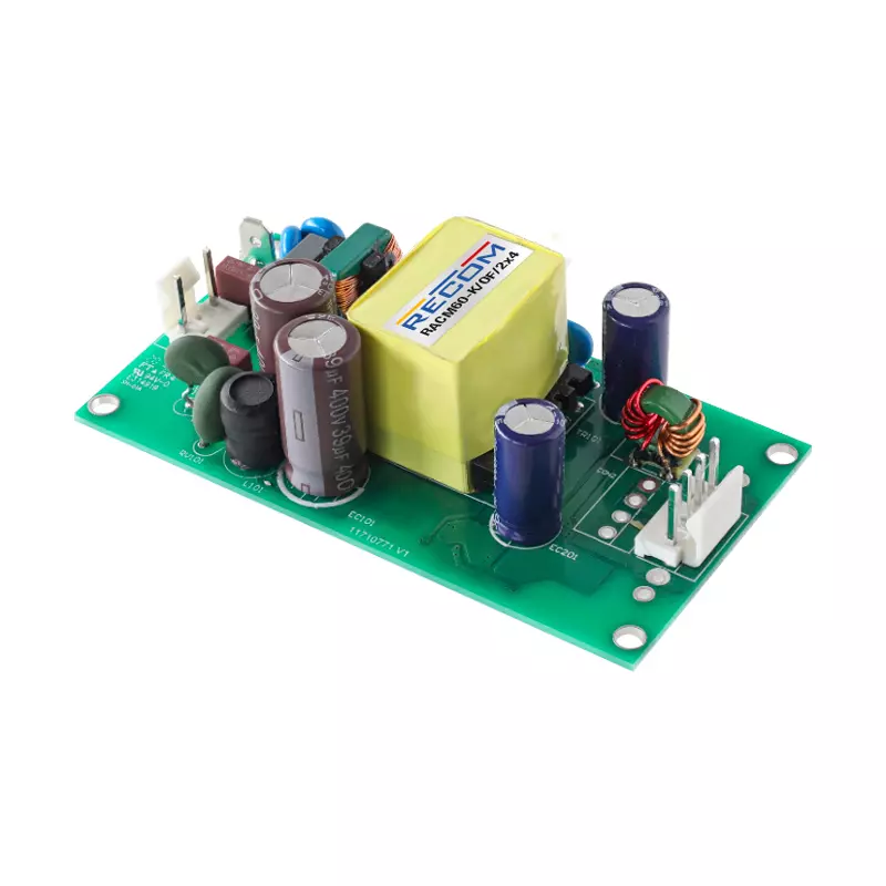
Figure 5 shows two different RECOM products (RACM60 and RACM550) that use the thermistor and thermistor plus relay methods.
Reducing input inrush current (DC/DC power supplies)
For a DC/DC converter, a thermistor could also be used as an inrush current limiter, but there can be start-up problems if the resistance is too high when the thermistor is cold and the DC/DC converter cannot draw enough current to start-up properly. A more common solution is to add an inductor to limit the inrush current. This has the added advantage of acting as an input filter and reducing conducted EMI interference when used as a Pi-Filter. The inrush current is split between the supply voltage capacitor, C1, and the inductor-limited input current required by C2 and the converter (shown dotted).
Fig. 6: Using an input pi-filter to reduce the inrush current for a DC/DC converter
For higher power DC/DC converters, the input inductor may need to be unacceptably large or expensive to adequately reduce the inrush current. Also, the filter has resonances which can cause over-voltage and even converter instability without damping techniques. An alternative is to use an active current limiting circuit, such as the soft-start circuit shown in the RECOM DC/DC Book of Knowledge), Chapter 4.7:
Fig. 7: Soft-start circuit using an N-channel MOSFET to bypass a current limiting resistor
On power-on, the transistor Q1 is off and the converter is supplied via the current limiting resistor Rlimit. The capacitor C1 is slowly charged up via the resistor R1. When the voltage exceeds the gate voltage of the MOSFET, it turns on and bypasses the current limiting resistor. R2 both limits the maximum voltage on the gate to safe levels by acting as a potential divider with R1 and also discharges C1 when the power is removed, to reset the protection.
Fig. 8: Alternative soft-start circuit using a P-channel MOSFET in the ohmic region to limit the inrush current
The circuit shown in Figure 7 uses a low-cost N-Channel MOSFET, but has the disadvantage that a high-wattage current limiting resistor Rlimit is needed. If there are space constraints, then Rlimit can be omitted and the channel resistance of the MOSFET used as current limiting, although this is not as well controlled as with a separate resistor. The circuit can also be inverted and used as a current limiting device on the positive rail with a P-Channel MOSFET operating with a resistor or in the ohmic region. When a separate resistor is not used, there is the added advantage that the MOSFET will also block a reverse polarity connection. Two or more MOSFETs can be wired in parallel to increase the current handling capacity, as can be seen in the example shown in Figure 9 (RECOM RPMD series).
Fig. 9: Input filter with active inrush current limiting MOSFETs used in parallel
We are here to help
Inrush currents can be a problem in some AC/DC and DC/DC applications, causing nuisance tripping of fuses or over-current protection in primary power supplies, or in severe cases, causing the failure of the converter. However, there are several techniques on offer to counteract the effects. If inrush current is a problem in your application, it is worthwhile contacting RECOM technical support or our experienced sales engineers for advice.
RECOM builds-in inrush current limiting in all of its higher power AC/DC power supplies, be they off-board or PCB mounting. Nevertheless, if many power supplies are connected in parallel to the same supply line, for example, in LED lighting applications, then even with individual inrush current limiting in each controlgear the combined current can still be a problem. Therefore, RECOM includes the maximum loading of automatic circuit breakers in the AC/DC LED driver datasheets, depending on the type (B, C or D) and current rating.