Planar transformers benefit DC/DC converter designs

3D model of a RECOM DC/DC converter with planar transformer
Transformers have long been a thorn in the side of DC/DC converter designers. They are bulky, expensive, and hard to manufacture. Find out how planar transformers boost quality and lower the cost of low-wattage DC/DC converter designs.

Planar versus toroidal transformers: what is the difference?

The transformer is at the core of any DC/DC converter design and is the most critical component in determining the overall performance.

Traditionally, transformers and inductors are wound components. Most mass-produced low-power DC/DC converters use hand-wound toroidal transformers; it is extremely difficult to develop an automatic manufacturing process for a transformer that requires up to six separate windings with a diameter core as small as 6mm with a 3mm hole. Manufacturers such as RECOM have developed automatic winding machines to manufacture such tiny toroidal transformers, but such solutions are very hard to find.

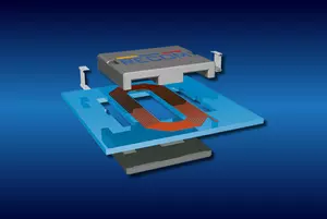
Planar magnetics have existed since the 1980s, but the manufacturing process was initially prohibitively expensive, so planar transformers had limited market penetration outside of specialized applications. However, as manufacturing technology has advanced, the cost of planar transformers has decreased, allowing for the development of new applications.

Planar transformer construction and design

Circuit board with electronic components
Fig. 1: The RPA100E-W series DC/DC converter shows the ferrite core surrounding the windings to form a planar transformer (source: RECOM)
A planar transformer or inductor uses the copper layers in a multilayer printed circuit board (PCB) to form the windings; a ferrite core surrounds the windings, as shown in Figure 1. In order to make the required number of turns, hidden vias are used to form connections from one PCB layer to the next. Multiple vias connected in parallel can carry sufficient current to make a useful miniature power transformer.

Figure 2 shows how a six-turn winding can be formed by stacking two layers connected with a hidden via. Observe how this arrangement places the two ends of the winding conveniently outside the ferrite core. The primary and secondary windings are typically interleaved to reduce leakage inductance. Using a printed circuit board gives a mechanically stable winding structure that is extremely consistent and lends itself to automated production. In addition, advances in multilayer PCB construction mean that the epoxy insulation between the windings can withstand high isolation voltages between primary and secondary circuits.

Three coil diagrams with different windings

Fig. 2: Construction of a 6-turn winding from two stacked layers plus a hidden via. (Source: RECOM)
The planar design does pose some challenges for the design and manufacturing teams. The difficulty of laying out multiple traces on a multilayer PCB means that planar transformers are best suited to DC/DC converter topologies that do not require complicated transformers; a half-bridge topology is a popular choice.

Even so, there is a practical and cost limit to the number of layers that can be used, so planar magnetics use high-frequency PWM modulators and driver circuits to reduce the number of turns and layers needed. The skin effect posed by these higher frequencies is the primary issue they cause. The charge carriers move more and more to the surface of a conductor as frequency increases, reducing its effective cross section and increasing the I2R losses. The conductors' flat (rectangular) design can offset this skin effect.

The multilayer construction has a high coupling capacitance, complicating the high-frequency PWM control. The coupling between the planar transformer and the associated conventional circuitry must be carefully managed to avoid termination losses. The proximity of the core gap and the layered winding can result in significant eddy current losses, and due to the different ratios of the number of turns, a separate PCB must be designed and tested for each input/output combination.

Once these problems are resolved, planar technology enables the construction of an extremely flat transformer capable of transmitting large amounts of power, allowing the DC/DC converter to have a very low height profile: the 100W converter in Figure 1 has a package height of only 11mm (0.4”)!

Other advantages of planar designs include better heat dissipation in the windings, a high-density design, low leakage inductance, and higher power densities.

Planar transformers move to lower power levels

The benefits described earlier make the planar transformer an indispensable component in high-power DC/DC converter technology, but RECOM is now incorporating planar technology into lower-wattage, smaller-sized converters.

Exterior and interior view of the RECOM RS12 series

Fig. 3: RECOM’s RS12-Z 12W DC/DC converter uses a planar transformer.
Figure 3 shows the external and internal construction of the RS12-Z regulated DC/DC series. This product uses a multilayer PCB with through-hole, buried, and blind vias to create an industry-leading 12W part in a very compact SIP package with a power density improvement of 150% compared to competing SIP8 products.

These regulated designs incorporated an integrated circuit on both the primary and secondary sides of the transformer. The primary-side IC is a wide-input, push-pull transformer driver. The output (secondary) side has a synchronous buck stage for accurate load regulation.

Even 1W and 2W DC/DC designs are in the pipeline, beginning with two product families. The RKK series DC/DC-Converter serves the industrial market with a very high isolation of 4kVDC/1s. The standard feature is the extended operating temperature range, which covers -40°C to +105°C without derating. The converters are IEC/EN/UL62368-1 certified and are suitable for IGBT driver applications.

The RYK series DC/DC converter is a cost effective, general-purpose, isolated converter with a built-in linear regulator that provides a regulated, load-independent output.

Changing to a planar transformer improves the quality of these designs by allowing for a more automated manufacturing process with reduced hand assembly. It is also easier to develop customized designs because it is not necessary to change transformer windings to accommodate different voltages.

The planar transformer is a technology whose time has come, and RECOM is making the most of it by adding planar transformers across its DC/DC converter product line.
Applications